


40
AXIS 225FD - Unit Connectors
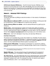
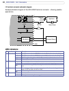
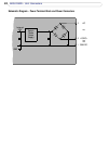
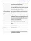
I/O terminal connector schematic diagram
Example schematic diagram of the AXIS 225FD terminal connector - showing possible
applications.
o
o
o
o
A
B
3
4
5
External Device
o
o
1
2
RS-485/422
Mains Power
24V DC
Appliance
Optional
Relay
Switch
o
o
o
o
o
o
o
o
o
7 GND
Switch, etc.
6
+3.3V
+3.3V
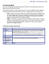
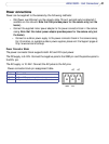
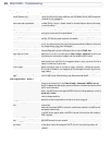
LED indicators:
1 Network Green Steady for connection to 100 Mbit/s network. Flashes for network activity.
Amber Steady for connection to 10 Mbit/s network. Flashes for network activity.
Red Flashes rapid red, together with the Status indicator, for hardware error.
Unlit No connection.
2 Status Green
Shows steady green for normal operation.
Amber
Shows steady amber during reset to factory default or when restoring settings.
Red
Slow flash for failed upgrade. Rapid flash, together with the Network indicator, for hardware
error.
3 Heater Green
Shows steady green if the connected power supply can deliver the correct voltage for the
heater (12V DC min 20W or 24V AC min 25VA).
Red
Incorrect voltage for the heater.
4 Power Green
Normal operation.
Amber
Flashes green/amber during firmware upgrade.
LED Function Color Description