


32 en | Test Software Global View Station 1000
F.01U.173.867 | 2.0 | 2010.11 Operations Manual Bosch Security Systems, Inc.
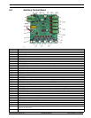
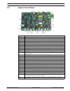
6.4 Voltage Touch Points
6.4.1 T3 SLED Power Input Indicator
– LED11 – indicates SLED controller power (not actual on/off state of illuminators)
– LED11 ON = SLED controller power on
– LED11 OFF = SLED controller power off
– Default: LED11 on (when system powered)
– Voltage should read 18 VDC ± 0.5 VDC
6.4.2 T4 Auxiliary Control Power Indicator
– LED12 – indicates system power
– LED12 ON = auxiliary board power on
– LED12 OFF = auxiliary board power off
– Default: LED12 on (when system powered)
– Voltage should read 24 VDC ± 0.7 VDC
6.4.3 T5 ZX700 Illuminator Output
– LED13 – indicates power to both ZX700
– LED13 ON = power output to ZX700 IR units on
– LED13 OFF = power output to ZX700 IR units off
– Default: LED13 off (power to ZX700 units off)
– Voltage should read 27 VDC ± 0.7 VDC
6.4.4 T6 SLED #1 Power Output Indicator
– LED14 – indicates power to SLED #1
– LED14 ON = power output to SLED #1 on
– LED14 OFF = power output to SLED #1 off
– Default: LED14 off (power to SLED #1 off)
– Voltage should read 15 VDC ± 0.7 VDC
6.4.5 T7 SLED #2 Power Output Indicator
– LED15 – indicates power to SLED #2
– LED15 ON = power output to SLED #2 on
– LED15 OFF = power output to SLED #2 off
– Default: LED15 off (power to SLED #2 off)
– Voltage should read 15 VDC ± 0.7 VDC