


34 en | Test Software Global View Station 1000
F.01U.173.867 | 2.0 | 2010.11 Operations Manual Bosch Security Systems, Inc.
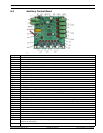
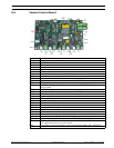
6.5.1 Reset Button
– SW1 – resets the board to default settings
– Resetting should be used when changing the system address or communication protocol
when the unit is powered.
6.5.2 System Communication
– T1 – Connects to system input
– to receive system communication from controller
– required for both simplex (2-wire configuration) and duplex (4-wire configuration)
– T2 – connects to system output
– to send system communication to controller – OPTIONAL
– required only for duplex (4-wire configuration)
– LED5 – indicates communication traffic to the system (LED always on when diagnostics
function engaged).
6.5.3 Camera Control Power Indicator
– LED6 – indicates presence of power
– LED6 ON = camera control board power on
– LED6 OFF = camera control board power off
– Default: LED6 on (when system powered)
– CN4 – connects to 12VDC for power input
6.5.4 Address Selection
– DIP1 – Switches 1-4
– Switches in various combinations of on/off will allow address setting of 1-16.
– Default address: 1
– Address MUST be the same for Auxiliary Control board (in PSU), Camera Control board
(in camera assembly), and Code Translator (in PSU).
– Refer to the GSV1000 Installation Manual.
6.5.5 Protocol Selection
– DIP1 – Switch 5
– Switch ON: Pelco D mode
– Switch OFF: Pelco P mode
– Default: Pelco D mode (switch off)
– Switch UP position is ON
6.5.6 Termination Jumpers
– For Biphase models, ensure Pelco D mode is enabled.
– JP3 / JP4 – controls the impedance of communication lines
– JP3 – T1 telemetry jumper
– JP4 – T2 telemetry jumper – ALWAYS CLOSED
– JP5 – diagnostics tool jumper – ALWAYS OPEN