Global View Station 1000 Test Software | en 33
Bosch Security Systems, Inc. Operations Manual F.01U.173.867 | 2.0 | 2010.11
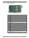
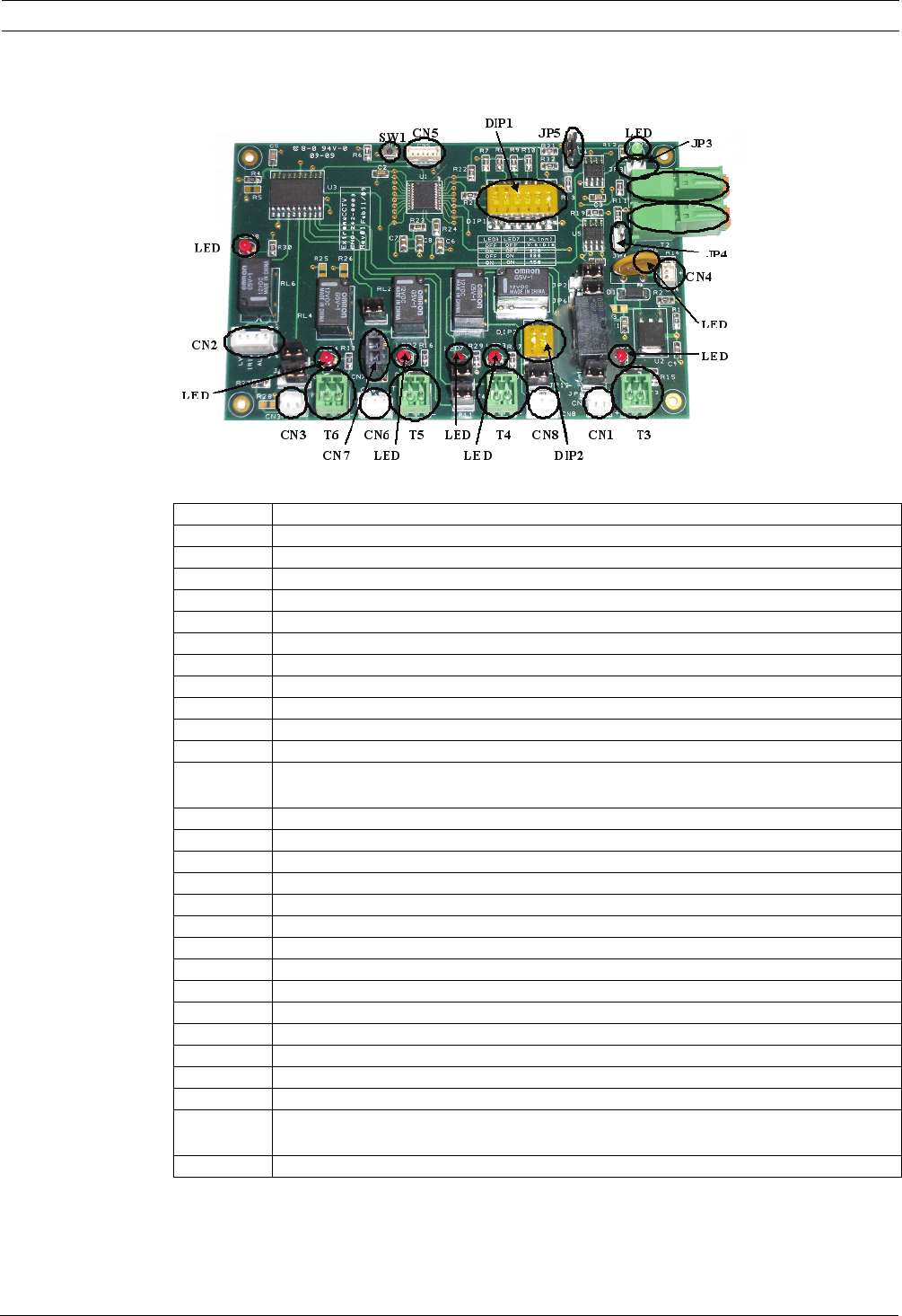
6.5 Camera Control Board
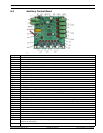
Figure 6.12 Camera Control Board
Component Description
SW1 Board reset button
T1 RS485/422 telemetry input to board
T2 N/A
T3 NC
T4 NC
T5 NC
T6 NC
LED1 Aux 1 Doubler status indicator
LED2 Aux 2 Wiper status indicator
LED3 Aux 5 IR-correction mode indicator (used with LED7)
LED4 Aux 6 D/N mode indicator
LED5 RS485/422 data input indicator (constantly on in SELF-TEST). Flashing when
receiving data
LED6 12 VDC input power indicator
LED7 Aux 5 IR-correction mode indicator (used with LED3)
LED8 Aux 4 iris control mode indicator
CN1 Aux 1 control connection to lens
CN2 Aux 4 control connection to lens
CN3 Aux 6 control relay to camera
CN4 12 VDC power input connection
CN5 Firmware programming connection
CN6 Aux 2 connection to wiper
CN7 Aux 2 24 V connection (for wiper park position)
CN8 Aux 5 control connection to lens
JP3 Protocol termination jumper (used with JP4)
JP4 Protocol termination jumper (used with JP3)
JP5 Protocol telemetry selection jumper (for PELCO D support only)
DIP1 Switches 1-4 for system address setting; switch 5 for Pelco P/D selection; switch
6 for diagnostics function on/off control
DIP2 IR correction controls (positions 1 and 2 should be ALWAYS OFF - DEFAULT)


