


16 en | On-Screen Display Menu Navigation AutoDome Modular Camera System
F01U064036 | 1.1 | 2007.01 VG4-200, VG4-300, VG4-500i Series User’s Manual Bosch Security Systems, Inc.
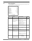
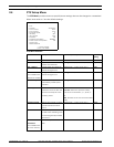
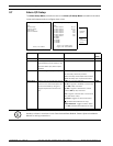
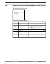
2.7 Alarm I/O Setup
The Alarm Setup Menu provides access to the Alarm I/O Setup Menu to establish the alarm
inputs and outputs and to configure alarm rules.
Alarm Setup Menu Choices:
Alarm I/O Setup Inputs Setup
Exit... Exit...
Inputs Setup... 1. Alarm Input 1 N.C.S.
1-7
Physical
Inputs
Outputs Setup... 2. Alarm Input 2 N.O.S.
Rule Setup... 3. Alarm Input 3 N.O.
Restore Defaults... 4. Alarm Input 4 N.C.
5. Alarm Input 5 N.O.
6. Alarm Input 6 N.C.
7. Alarm Input 7 N.O.
8. NONE
8-12
Command
Inputs
9. NONE
10. NONE
11. NONE
12. NONE
Focus / Iris: Select Type
Focus / Iris: Select Right / Left: Select Mode
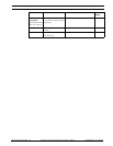
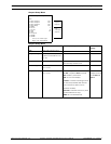
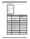
Menu Description Sub-menu / Description Default
Setting
Exit Saves and exits the menu.
Inputs Setup Defines physical inputs or events and
commands that can be used in a rule.
There are twelve (12) alarm inputs
available.
Inputs 1-7 Defines the type of physical input. N.O.: Normally open dry contact.
N.C.: Normally closed dry contact.
N.C.S.: Normally closed supervised contact.
N.O.S.: Normally open supervised contact.
N.O.
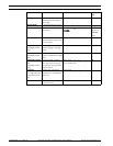
Inputs 8-12 Defines input commands that can be
used in a rule. Command inputs can
also be customized by using non-
assigned keyboard command num-
bers.
NONE: No command defined.
Aux On: Programs a standard or custom key-
board ON (1-99) command.
Aux Off: Programs a standard or custom
keyboard OFF (1-99) command.
Shot: Programs a Preset shot or scene from
1-99. (200 Series 1-64).
AutoTrack: Triggers an alarm when set to
ON. (Available with 500i Series only).
Motion Detection: Triggers an alarm when
set to ON. (Available with 500i Series only).
NONE
i
NOTICE! Alarm inputs 1 and 2 provide tamper detection, if programmed as supervised, for
breaks or shorts in an alarm circuit. See the AutoDome Modular Camera System Installation
Manual for wiring instructions.