


AutoDome 600 Series Analog PTZ Camera Advanced Features | en 45
Bosch Security Systems, Inc. User Manual F.01U.270.005 | 2.0 | 2012.06
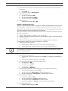
4. Set up the Alarm Rule (for this example use Rule 1). Select the Inputs from the Rule
Setup menu:
a. Select Rule 1.
b. Set the first input to Alarm Input 1.
5. Select the outputs:
a. Set the first output to OSD.
b. Set the second output to Shot 7.
c. Set the third output to Transmit.
6. Enable the rule:
– Highlight Enabled and select YES.
Example 2: Advanced Alarm Rule
Scenario: A VG5 AutoDome located at an airport is set to AutoPan Between Limits from the
parking garage to the airport terminal. The gate entering the airport has an alarm contact
connected to the AutoDome, and the perimeter fence in the area of the gate has an infrared
(IR) motion detection sensor connected to the AutoDome.
When both the gate contact and motion detector alarms are activated at the same time, we
want the alarm rule to:
1. Flash an OSD message (***ALARM 2***) on the monitor.
2. Stop the AutoPan and move the camera to a saved position (Shot 5) viewing the fence.
3. Turn on AutoTrack.
4. Transmit a Bilinx signal to the head end system to trigger an alarm response.
The sequence to program this alarm rule example is as follows:
1. Wire and set the alarm Input(s).
a. Wire the motion detector to Input 1. (This circuit is normally open.)
b. Wire the gate alarm contact to Input 5. (This circuit is normally closed.)
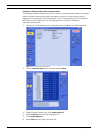
2. From the Inputs Setup menu:
a. Ensure Input 1 (the motion detector) is set to N.O. (This setting is the default for
Input 1.)
b. Ensure Input 5 (the gate contact) is set to N.C.
3. Set the alarm Outputs from the Outputs Setup menu:
a. Set Output 5 to OSD.
b. Set Output 6 to Transmit.
c. Set Output 7 to Shot 5.
d. Set Output 8 to AutoTrack.
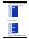
4. Set up the Alarm Rule (for this example use Rule 2). Select the alarm Inputs:
a. From the Rule Setup menu select Rule 2.
b. Set the first input to Alarm Input 1. (The motion detector.)
c. Set the second input to Alarm Input 5. (The gate alarm contact.)
5. Select the alarm Outputs:
a. Set the first output to OSD.
b. Set the second output to Shot 5 viewing the fence.
c. Set the third output to AutoTrack and select Latched.
d. Set the fourth output to Transmit (a Bilinx signal to the headend).
6. Enable the alarm Rule:
– Highlight Enabled and select YES.
NOTICE!
For instruction on wiring alarm and relay connections, see the AutoDome Modular Camera
System Installation Manual.