CHAPTER 4 INTERFACE
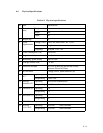
4.1 Physical Specifications
4.2 SCSI Bus
4.3 Bus Phases
4.4 Commands
4.5 Status
4.6 Messages
4.7 Command Sequence
4.8 Status Transition of Logical Unit
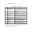
4.9 Error Table
4.10 Items for Specifying Window and Subwindows
This image scanner and the host are connected via an 8>bit parallel interface. The interface
follows the ANSI (American National Standards Institute) SCSI 2 (Small Computer System
Interface 2) Revision 10c.
This chapter provides an overview of SCSI (minimum information necessary for
understanding this scanner), as well as descriptions peculiar to the scanner. For details of
SCSI, refer to the ANSI standard.
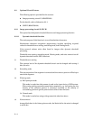
The following terms are needed to understand this section.
f SCSI device: A host adapter or a target controller that can be attached to the SCSI
bus
f Initiator: An SCSI device (usually a host system) that requests an I/O process to be
performed by another SCSI device (a target)
f Target: An SCSI device that performs an operation requested by an initiator
f Logical unit: A physical or virtual peripheral device that is addressable through a
target
Range of support
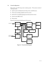
(1) System configuration
This scanner operates under the multiinitiator, multitarget environment. An
initiator function is not provided. This scanner incorporates an integrated target
and logical unit (image scanner).
4 $ 1


