(2) Physical specifications
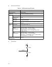
Table 4.1 SCSI physical specifications
Item Specification
Driver/Receiver
Connector
Single>ended
50 Contact Shielded Low Density
Cable Max. cable length
Characteristic
impedance
Cable type
Stub wire
Signal
level
Terminator
Driver/receiver
Output
characteristics
Input
characteristics
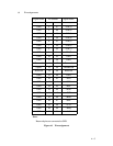
Connector pin assignments
for signal lines
6 m
132 ]
25 signal twisted pair
e 0. 1 mm (from main cable in scanner to internal
wiring)
See the figure under (3).
Open collector or three> state driver
Low level (true) = 0. 0 to 0. 5 VDC
High level (false) = 2. 5 to 5. 25 VDC
Output current = 48 mA (corresponding output
voltage e 0. 5 V)
Low level (true) = 0. 0 to 0. 8 VDC
High level (false) = 2. 0 to 5. 25 VDC
Input load = -0. 4 mA max. (at 0. 4 V input voltage)
Input hysteresis = 0. 2 VDC min.
See (4).
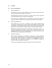
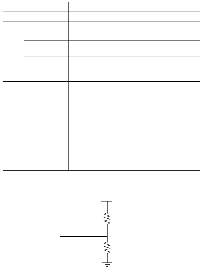
(3) Termination
+5 V
-signal
220 ]
330 ]
4 $ 4


