


C156-E097-01EN 1 - 7
1.2.2 Configuration
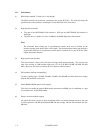
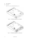
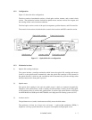
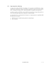
Figure 1.3 shows the drive configuration.
The drive consists of mechanical sections, a fixed optics section, actuator, and a control circuit
section. The mechanical sections include the spindle motor, actuator section, bias magnet, and
the cartridge folder vertical motion mechanism.
The fixed optics section consists of the optical components, position detector, and LD controller.
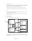
The control circuit sections include the drive control circuit section and SCSI controller section.
Figure 1.3 Optical disk drive configuration
1.2.3 Mechanical sections
(1) Optical disk cartridge load/eject
The system includes a cartridge mechanism which lowers the optical disk cartridge and mounts
(loads) it on the spindle motor automatically when the optical disk cartridge is fully inserted in
the optical disk drive’s disk slot, and a mechanism which automatically ejects the cartridge when
the Eject button on the front panel is pressed.
(2) Spindle motor
The optical disk cartridge’s hub and the spindle motor’s shaft are connected magnetically.
Therefore, if the spindle motor’s shaft is rotating, the disk medium is rotating at the same speed.
A DC brushless motor is used for this spindle motor. It realizes high speed rotation at 4558 rpm
for MCE3064SS and 3600 rpm for MCF3064SS, and a high precision rotating system (±0.1%).
(3) Actuator section
The positioner moves (seeks) a head actuator radially across the disk surface.
The positioner is driven by a linear voice coil motor. A pulse-width modulation (PWM) is
adopted as a driving system and realizes low power consumption and high-speed access.
Fixed optics sectionActuator section
Control circuit section
Spindle motor
Optical disk cartridge