


C156-E097-01EN 3 - 15
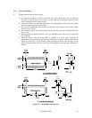
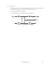
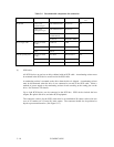
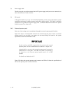
(1) Power supply connector
Figure 3.14 shows the shape and pin assignment of the DC power supply input connector.
Figure 3.14 Power supply connector
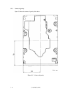
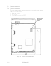
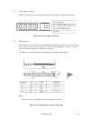
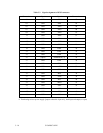
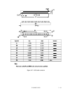
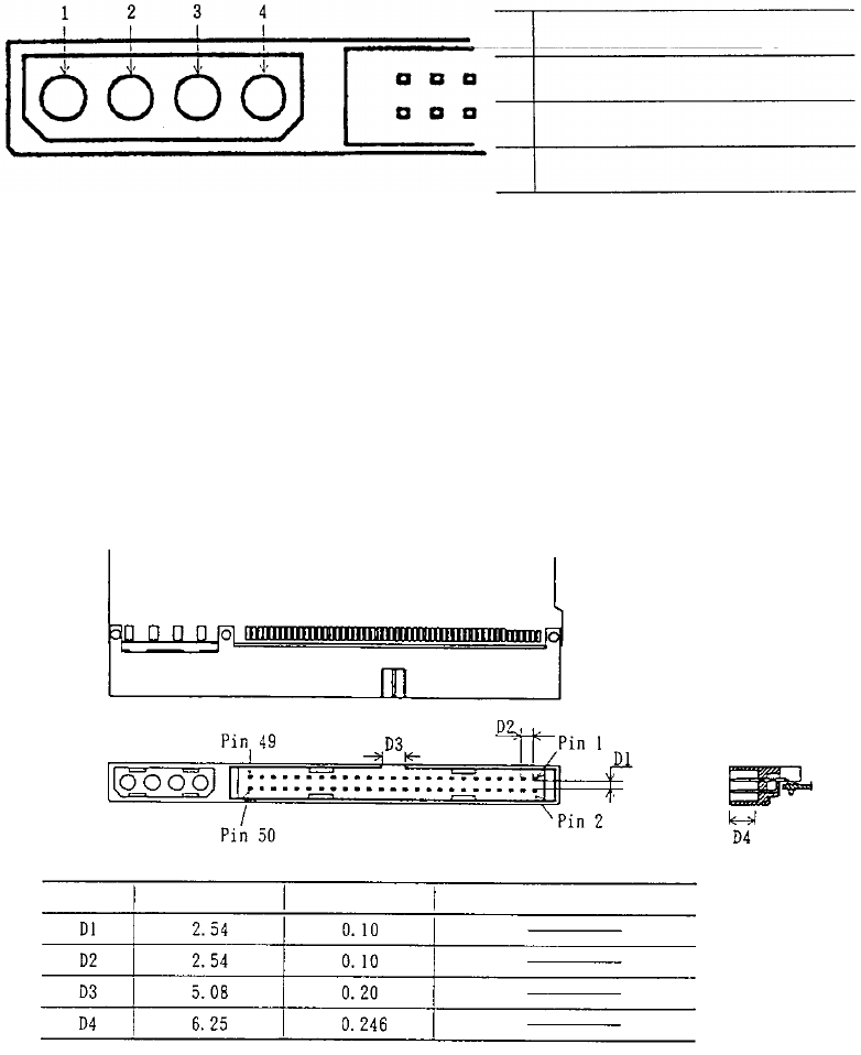
(2) SCSI connector
The connector for the SCSI bus is an unshielded standard connector with two rows of 25 pins
on 2.54 mm (0.1 inch) centers. Figure 3.15 shows the SCSI interface connector. Table 3.3
shows the signal assignment of the SCSI bus connector.
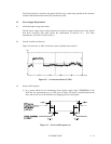
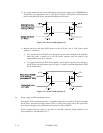
See Chapter 7 for details on the electrical requirements of the interface signals.
Note:
Tolerance is ±0.127 mm (0.005 inch) unless otherwise specified.
Figure 3.15 SCSI interface connector (drive side)
1 +12 VDC or N.C.
2 +12 VDC RETURN (GND) or N.C.
3 +5 VDC RETURN (GND)
4 +5 VDC
Symbol mm Inch Remark