


3 - 12 C156-E097-01EN
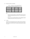
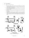
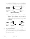
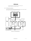
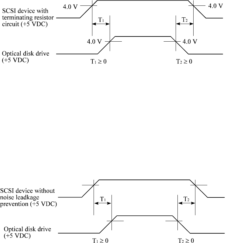
b) In a system which does not use the terminating resistor power supply signal (TERMPWR) of
the SCSI bus, the requirements for +5 VDC given in Figure 3.10 must be satisfied between
the drive and the SCSI device with the terminating resistor circuit.
Figure 3.10 Power on/off sequence (2)
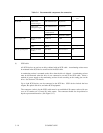
c) Between the drive and other SCSI devices on the SCSI bus, the +5 VDC power on/off
sequence is as follows:
• In a system with all its SCSI devices designed to prevent noise leakage to the SCSI bus
when the power is turned on or off, the power sequence does not matter if the
requirement in (a) or (b) is satisfied.
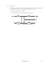
• In a system containing an SCSI device which is not designed to prevent noise leakage to
the SCSI bus, the requirement given in Figure 3.11 must be satisfied between the SCSI
device and the drive.
Figure 3.11 Power on/off sequence (3)
(4) Power supply to SCSI terminating resistor
If the power for the terminating resistor is supplied from the drive to other SCSI devices through
the SCSI bus, the current-carrying capacity of the +5 VDC power supply line to the optical disk
drive must be designed with consideration of an increase of up to 900 mA.
Select a method of power supply to the drive in accordance with the setting terminal of the
optical disk drive. See Subsection 4.3.3.
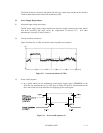
0.5V
4.75V
0.5V
4.75V