4 - 14 C156-E097-01EN
4) Connect the SCSI cable.
5) After each cable connector is connected, secure the cable so that the cable does not touch the
drive or the parts on the PCA or obstruct the flow of cooling air in the system cabinet.
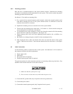
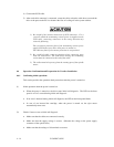
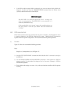
1) Be careful of the insertion directions of SCSI connectors. For a
system in which the terminating resistor power is supplied via the
SCSI cable, connecting connectors in the wrong direction may
cause the following:
The overcurrent protection fuse of the terminating resistor power
supply (SCSI device) may blow when power is turned on.
The cable may burn if overcurrent protection is not provided.
2) Be careful of cable connector positions when connecting more
than one SCSI device. The SCSI device having the terminating
resitor must be connected to the end of the cable.
3) The cables must be kept away from the rotating part of the spindle
motor.
4.6 Operation Confirmation and Preparation for Use after Installation
4.6.1 Confirming initial operations
This section provides the operation check procedures after the power is turned on.
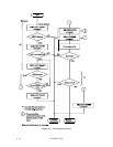
(1) Initial operation when the power is turned on
• When the power is turned on, the drive starts initial self-diagnosis. The LED on the front
panel is on for 3 seconds during initial self-diagnosis.
• If an error is detected during initial self-diagnosis, the LED on the front panel blinks.
• In case of not inserted the cartridge, when the power is turned on, the eject motor
automatically turns once.
(2) Checks if errors occur at initial self-diagnosis
• Make sure that the cables are connected correctly.
• Make sure that the supply voltage is correct. (Measure the voltage at the power supply
connector of the optical drive.)
• Make sure that the settings of all terminals are correct.


