


2. General Description
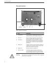
Rear panel controls
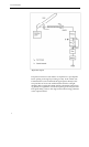
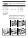
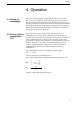
Fig. 6. Control unit. Rear panel.
No. Item
Description
17
18
19
20
21
22
Mains voltage selector
Fuse holder
Signal outputs
Mains inlet
Optical unit inlet
Ground terminal
Selects mains voltage 110, 130, 220 and 240 V
Mains fuses:
1 x 250 mA for 110-130 V 60 Hz
1 x 125 mA for 220-240 V 50 Hz
The output signal is a 10 mV DC signal. The
terminals are connected to a potentiometric
recorder via shielded cables supplied. The
UV-1 is normally earthed via the mains ground
Inlet for the mains cable
Inlet for the optical unit
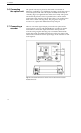
To connect the shield of an output signal cable
Note:
Do not attempt to ground the control unit via the recorder
ground as the UV-1 is grounded via the mains ground.
10