


3. Installation
3. Installation
3.1 Site
UV-1 should be installed on a stable, flat surface away from all sour-
requirements
ces of vibration. The atmosphere should be free of both excess humi-
dity and corrosive or contaminated vapours which may form deposits
on the component in the optical path.
UV-1 can be installed either in a coldroom or at ambient temperature
in the laboratory. To minimise drift, the temperature should be kept
constant. UV-1 optical unit should be positioned away from all sour-
ces of draught, heat and direct sunlight. UV-1 should be placed away
from any compressor and the fan stream from coldboxes and col-
drooms.
The UV-1 may be operated ambient temperatures in the range
0-40 °C (20-30 °C at full specifications).
One mains power point is required to operate UV-1. Separate power
points are required for all ancillary equipment, such as recorder.
The power consumption of the monitor is max 20 VA.
3.2 Unpacking
Note:
It is important that the interference filters and flow cells
should not be handled during unpacking. For protection of
these items they should remain in their packing materials
until required for use.
Carefully unpack the UV-1. Check the contents against the packing
list supplied. Inspect for any damage that may have occurred during
transit. Report any damage immediately to the local
GE Healthcare
representative and to the transport company concerned. Save
the packing material if future transport can be foreseen.
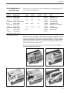
3.3 Electrical
The instrument is supplied with mains cables and fuses for both
connections
100-130 V and 220-240 V operation.
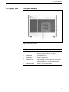
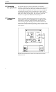
1.
Ensure that the mains switch (Fig. 5:16) on the front panel of
the control unit is in the OFF position.
2.
Select the correct value of fuse from the fuse kits supplied.
For 110-130 V operation, use the 250 mA fuse supplied.
For 220-240 V operation, use the 125 mA fuse supplied.
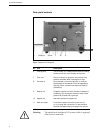
Insert the fuse into the fuse cap, and then fit the fuse cap into the
fuse holder on the rear panel (Fig. 6:18) of the instrument.
3.
Check that the mains voltage selector (Fig. 6:17) on the rear
panel of the control unit is set to the mains voltage in the
laboratory. If necessary, turn with a thick bladed screwdriver the
mains voltage setting until appropriate setting is indicated in the
small window.
Note:
Use the 220 V setting for a 230 V mains outlet.
11