


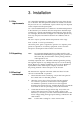

3. Installation
3.6
3.7
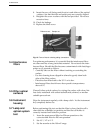
Connecting
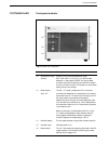
The optical unit may be placed on the bench or mounted on
the optical unit
laboratory scaffolding. For scaffolding mounting, mount the support
rod on the optical unit. The rod may be mounted horizontally or
vertically (Fig. 4:9). Tighten the the Allen screw firmly. The optical
unit should be placed as close as possible to the column outlet.
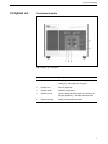
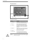
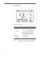
Connect the cable from the optical unit to the 1 l-pin socket on the
back of the control unit (Fig. 6:21). The plug has a snap lock.
To remove it, squeeze the ribbed sides firmly and pull.
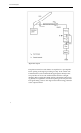
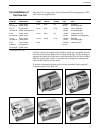
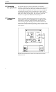
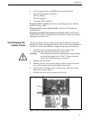
Connecting a
There is one 10 mV signal output port on the rear panel of the
recorder
control unit. It is for use with GE Healthcare recorders or similar
instruments. Connect the output terminals to the input of the
recorder, using a signal cable (Fig. 12). Connect the shield of the
signal cable to the grounded terminal port on the rear panel of the
control unit. Choose the 10 mV input range on the recorder for full
scale response.
Fig. 12. Connections between the control unit and a dual channel recorder
Recorder REC 102.
14