


WIRELESS NETWORK IP CAMERA User’s Guide
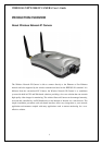
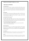
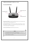
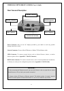
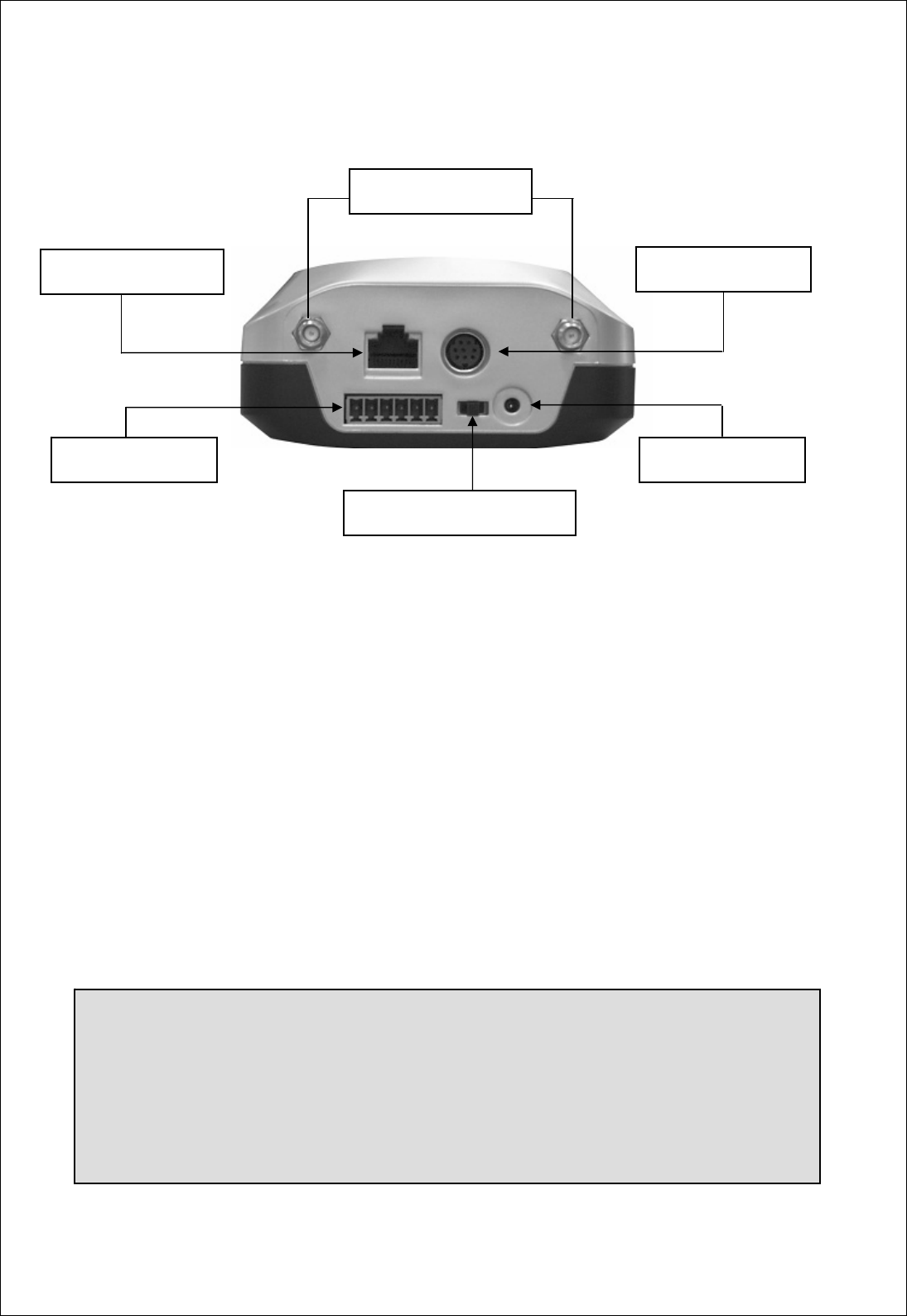
Rear View and Description
Power Connector: Only use the AC Adapter provided by your dealer to avoid any possible
damage from electric shock.
Network Connector: Connect 10baseT Ethernet or 100base TX Fast Ethernet cable.
GPIO Connector
: To connect external devices such as infrared Sensors, alarms, or motion
detectors (please refer to Appendix F – The I/O Connector).
RS232 Cable Connector: To connect external devices such as external pan/tilt/zoom mechanism,
or directly to a serial port for configuration (please refer to Appendix G - RS 232 Cable).
11
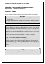
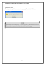
IMPORTANT
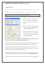
1. After connecting the Ethernet network, the status led (Green) on the very right side on camera
should be turn on. If not, check your network connection.
2. Connect wireless IP Camera to Ethernet network. The default position of camera’s network
switch is at center position it means both network i.e. user can use camera in any network.
Network Connector
Antenna Connector
RS 232 Connector
Power Connector GPIO Connector
LAN/ WLAN-LAN/ WAN