


WIRELESS NETWORK IP CAMERA User’s Guide
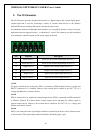
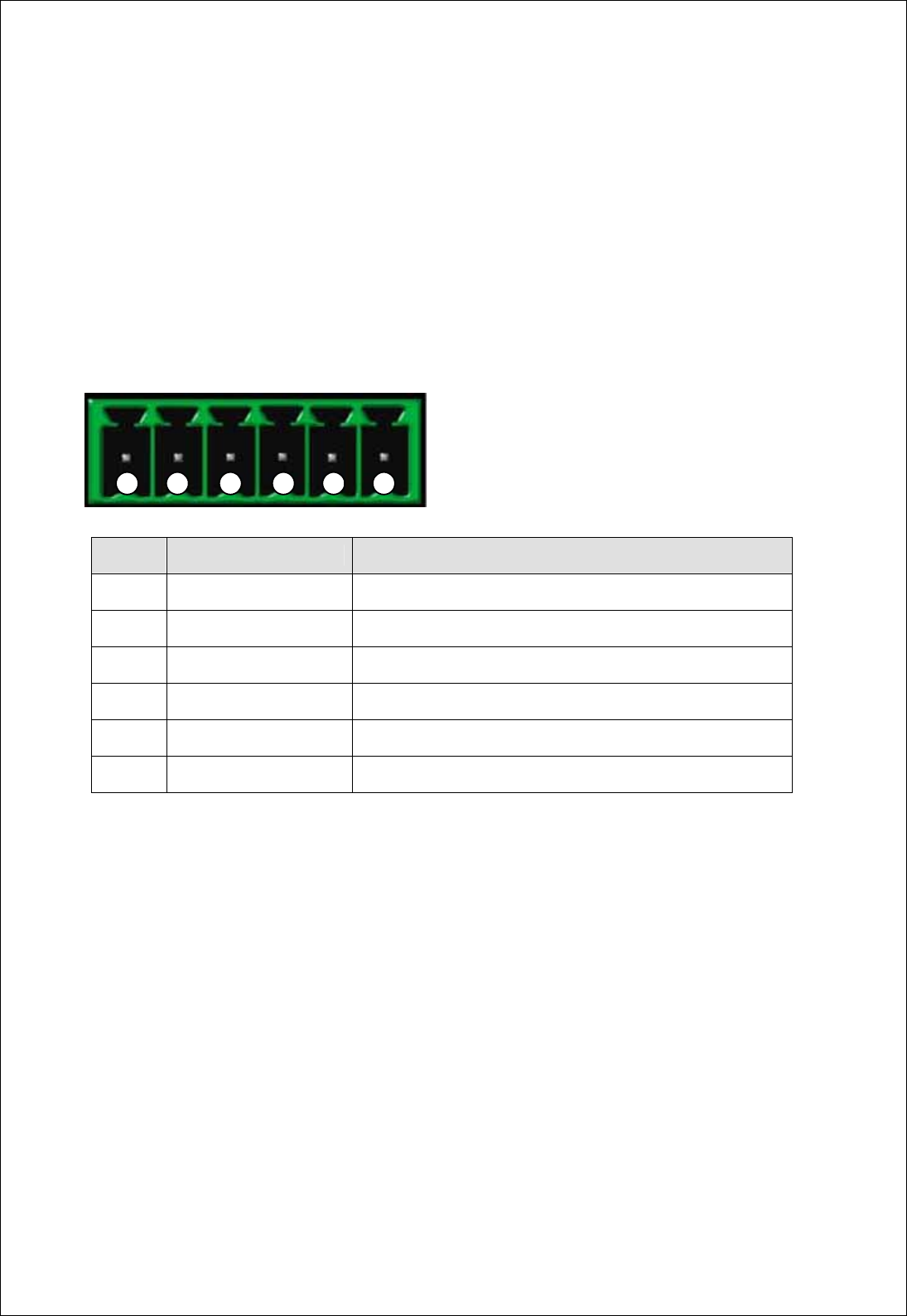
F. The I/O Connector
The I/O Connector provides the physical interface to a digital output, and a single digital photo-
coupled input that is used for connecting a variety of external alarm devices to the Wireless
Network IP Camera; including, IR-sensors, switches and alarm relay.
In combination with the configurable alarm facilities, you can quickly develop a variety of security
applications that are triggered on time – or alarm based – events. The connector can also be utilized
as an alternative connection point for DC power supply to the unit.
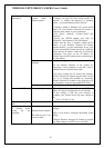
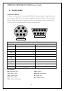
1-2 PIN
To supply external devices with power. PIN1 is connected to GND terminal of device’s power and
PIN2 is connected to (+) terminal. However, the external device should be less DC 12V as a
voltage and 200mA as an electric current.
3-4 PIN
PIN3 is connected to (+) terminal of external output device; PIN4 is connected to GND terminal of
it. Wireless Network IP Camera makes external output device operating by sending signal to
external output device.
However, the external device should be less DC 12V as a voltage and
200mA as an electric current.
5-6 PIN
PIN5, 6 are connected to the signal output terminal of external input device such as infrared sensor
or alarm sensor. (This signal output terminal should be “Normally Open” type.)
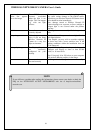
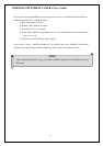
NO Function Description
1
Power GND (-) Power for the external input/output devices (-)
2
Power DC12V (+) Power for the external input/output devices (+)
3
Digital Out (+) Output to the external output devices (+)
4
Digital Out GND (-) Output to the external output devices (-)
5
Digital In (+) Input for the external input devices (+)
6
Digital In GND (-)
Input for the external input devices (-)
66
1 2 3 4 5 6