4. POWER SUPPLY
40
STATUSSHUTTER
MENU
FILTER
3200k
1
5600k+1/8ND
2
5600k+1/64ND
3
ALARM
MONITOR
OPERATE
NG
G
A
IN
O
U
T
P
U
T
W
H
T
.B
A
L
V
T
R
ON OFF
AUTO IRIS
LOLUX
BACK L
NORMAL
SPOT L
STRETCH
NORMAL
COMPRESS
LIGHT
ON
OFF
COUNTER
AUDIO SELECT
MANUAL
AUTO
CH-1 CH-2 CH-1 CH-2
REAR
FRONT
RM
AUDIO INPUT
MODE
CTL
TC
UB
CH-1
MIX
CH-2
RESET
OPERATE/WARNING
MONITOR
SELECT
CH-1
AUDIO
LEVEL
CH-2
VTR
ON
OFF
INCOM
MIC
INCOM
MIC
LEVEL
POWER
OFFRM
DC IN
/BATT.
CALL
CARBON
DYNAMIC
FULL AUTOBLACK
EFBATT
E BATT
WARNING
indicator
Remaining battery
power indication
TALLY
lamp
REC
BATT
LOW BATTERY
ALARM
Viewfinder
BATT lamp
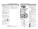
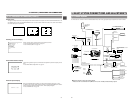
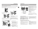
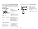
REMAINING BATTERY POWER DISPLAY
To display the remaining battery power accurately, set the
VCR Setup Menu item No. 396 BATTERY TYPE according
to the type of the battery pack in use.
☞ See page 75.
The status of the remaining battery power can be checked by
the remaining battery power indication.
☞ See page 24.
Ⅲ When the remaining battery power is nearly exhausted, the
following warning messages will appear. In this case, replace
with a fully charged battery as soon as possible.
● Remaining battery power indication:
Segment bar and "BATT" indicator start to blink
● WARNING indicator and TALLY lamp blink
● Viewfinder:
• BATT lamp lights.
• TALL lamp blinks.
• During status 1 mode, the voltage display flashes.
● Alarm sound beeps
After the remaining battery power warnings appear, the
GY-DV550 automatically stops operation if the battery
power operation is continued.
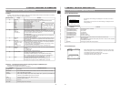
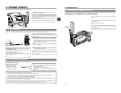
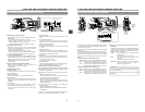
Operating Time with Battery Pack
When the VF-P115B is used as the viewfinder and a fully
charged battery pack is attached, the approximate continuous
operating time is as follows:
● Battery operating time may differ depending on the number
of times the battery has been charged, charging conditions
and the operating environment, etc. Use the values in the
table on the left for approximate reference times.
● Operating time is reduced in areas with a cold environment.
● Operating time is reduced when the power zoom lens is used
frequently.
PRECAUTIONS FOR THE BATTERY PACK
● When the battery pack is not in use, it must be stored in a
cool, dry place.
Do not leave the battery pack in a place where it might be
subject to a high temperature (under direct sunlight in a car,
etc.), this could cause leakage of the fluid or shorten service
life.
● When the terminal section of the battery pack gets dirty, the
operating time will be shortened.
● If the operating time becomes greatly reduced even
immediately after recharging, the service life of the battery
pack is nearly finished. Purchase a new battery pack.
Recharging
● Recharge the battery pack after completely discharging it.
Repeated recharging with residual charge remaining could
result in reduced battery capacity.
● If the battery capacity is reduced by repeating incomplete
recharging, or recharging without discharging, once discharge
the battery pack completely, then recharge it to restore the
battery capacity.
● If the battery pack is recharged with its internal temperature
raised immediately after use, recharging may not be
performed completely.
4-2 Battery Pack Operation (Cont'd)
Battery Pack Continuous Operating Time (at 25 ˚C)
NP-1B 60 minutes
Magnum 14 130 minutes
NP-L40 80 minutes
4. POWER SUPPLY
39
4.
5.
5.
3.
3.
3.
1.
2.
4.
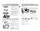
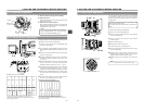
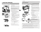
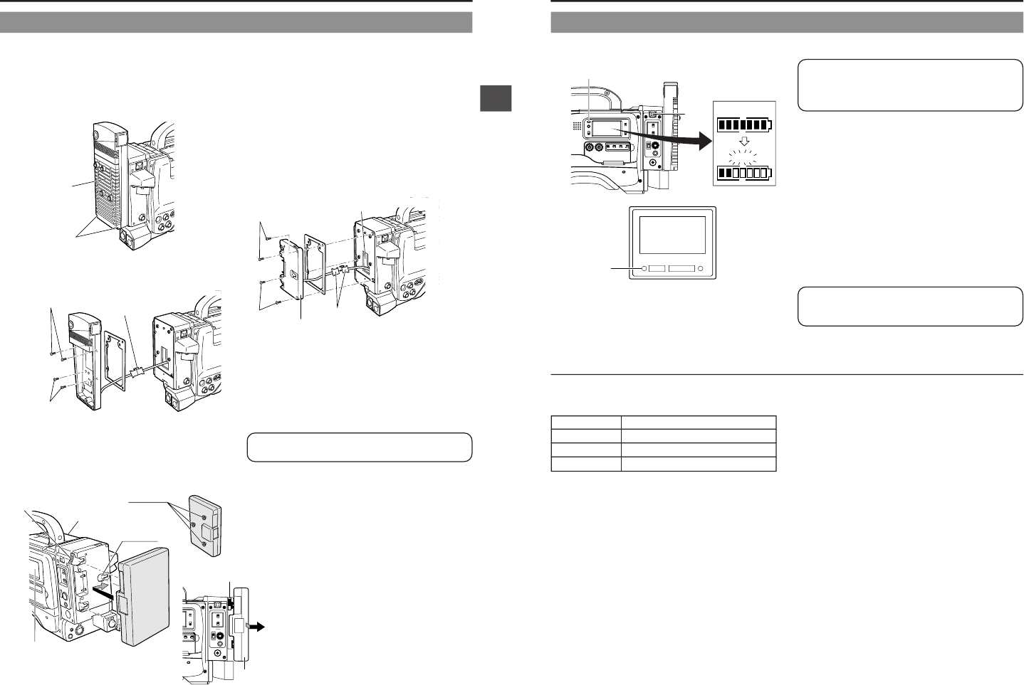
Connect the connectors protruding from the GY-DV550 with
the connectors on the battery holder.
* Following connection of the connectors, insert them into
the connector compartment.
5.
Secure the battery holder to the GY-DV550 with the four
mount screws provided with the battery holder.
*Take care not to pinch the wires. This could result in
damage.
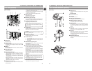
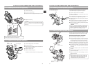
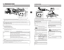
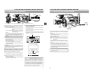
To use an Anton-Bauer battery pack (Propack 13/14, Trimpack 13/14, Magnum 13/14, Compack 13/14 Series), it is necessary to
detach the battery case from the GY-DV550 and replace it with the Anton-Bauer battery holder. Use the following battery holder.
• Battery holder: Anton-Bauer QRQ27
Detaching the Battery Case From the GY-DV550 and Attaching The Anton-Bauer Battery
1.
Remove the two black screws A on the battery case.
2.
Remove the lower half of the battery case cover in the
downward direction.
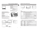
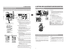
Attaching and Detaching an Anton-Bauer Battery Pack
Attaching the Battery Pack
1.
Align the 3 guide pins of the battery pack with
the guide holes on the battery holder, and push
straight to insert the battery pack.
The battery cannot be attached properly if the
guide pins are not inserted straight.
2.
Slide the battery pack toward the side panel
where the cassette cover is located until it clicks.
Now the battery pack has been attached.
Detaching the Battery Pack
Ⅲ While pushing and holding the release lever, slide
the battery pack toward the side panel where the
LCD display is located, then pull the battery pack
outward to remove.
3.
To remove the battery case, remove the four screws B fixing
the battery case and the connector connecting the battery
case to this unit.
4-2 Battery Pack Operation (Cont'd)
Black screw A
Mount screw
B
LIGHT
ON
OFF
COUNTER
CH-1 CH-2
REAR
FRONT
RM
AUDIO INPUT
MODE
CTL
TC
UB
VTR
ON
OFF
INCOM
MIC
INCOM
MIC
LEVEL
POWER
OFF
RM
DC IN
/BATT.
CALL
CARBON
DYNAMIC
Connector
Mount screw B
Guide pins
Battery
pack
(Trimpack)
Release
lever
Cassette cover
side panel
Guide holes
(x3)
Side panel
with display
Battery
Release lever
Anton-Bauer
Battery holder
USING AN ANTON-BAUER BATTERY PACK
Connector
Compartment


