13. FEATURES OF THE CAMERA SECTION
88
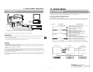
Ⅲ Outline
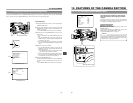
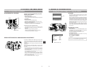
The following operation allows the alignment of the shutter
speed of the camera with the variable scanning rate of a
computer monitor or display.
When a computer monitor screen or display is shot with the
camera, a bright horizontal line indicating excessive exposure
is displayed in cases when the scanning rate of the monitor
is faster than the shutter speed of the camera. A dark
horizontal line indicating insufficient exposure is displayed in
cases when the monitor's scanning rate is slower than the
camera's shutter speed.
The scanning frequency of a monitor varies due to various
reasons during the computer operation. Adjust the scanning
rate to obtain a stable image while observing the image in
the viewfinder.
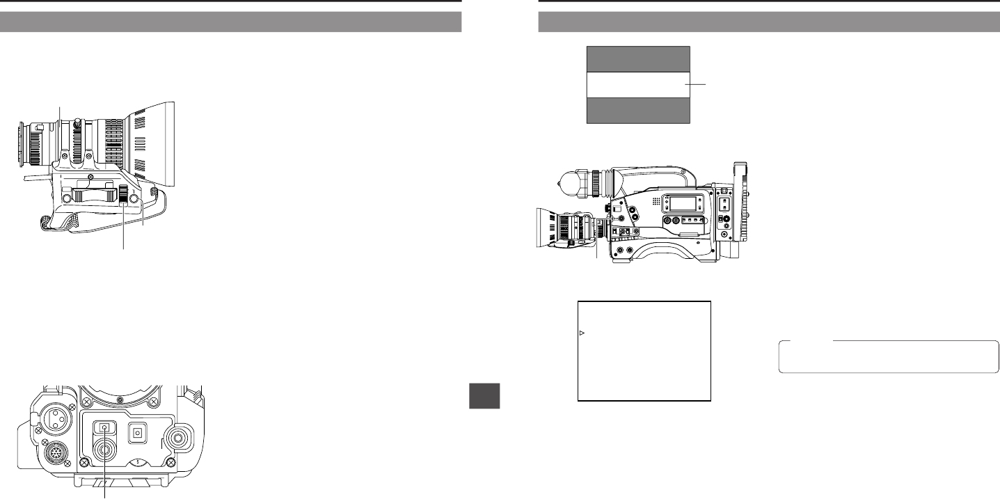
Ⅲ Variable Scan [V.SCAN]
• Basic operation
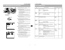
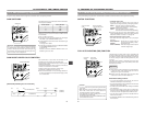
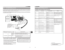
Set the SHUTTER item on the OPERATION MENU screen
to VARIABLE. Then move the SHUTTER knob upwards or
downwards to change the shutter speed.
(The speed is displayed on the viewfinder screen.)
• Compatible frequencies
The variable scan function is compatible with scanning
frequencies in the following range.
60.1 Hz to 2084.6 Hz (U MODEL)
50.1 Hz to 2067.8 Hz (E MODEL)
This function is not compatible with slow-speed computer
monitors with a vertical scanning speed of 50 Hz.
Video monitor
Band
13-3 Shooting the Screen Image on a Computer Monitor
OPERATION MENU screen
SHUTTER
STATUS
MENU
FILTER
3200k
1
5600k+1/8ND
2
5600k+1/64ND
3
ALARM
MONITOR
OPERATE
NG
GAIN
OUTPUT
WHT.BAL
V
TR
ON OFF
AUTO IRIS
LOLUX
BACK L
NORMAL
SPOT L
STRETCH
NORMAL
COMPRESS
LIGHT
ON
OFF
COUNTER
AUDIO SELECT
MANUAL
AUTO
CH-1 CH-2 CH-1 CH-2
REAR
FRONT
RM
AUDIO INPUT
MODE
CTL
TC
UB
CH-1
MIX
CH-2
RESET
OPERATE/WARNING
MONITOR
SELECT
CH-1
AUDIO
LEVEL
CH-2
VTR
ON
OFF
INCOM
MIC
INCOM
MIC
LEVEL
POWER
OFFRM
DC IN
/BATT.
CALL
CARBON
DYNAMIC
FULL AUTOBLACK
SHUTTER dial
D
--- OPERATION ---
SCENE F I LE A
ASPECT RATIO :4:3
LE
SHUTTER :VARIAB
:NONE
:0dB
dB
FAW
GA IN L
GA IN M : 9d B
GA IN H : 18
:OFF
SMOOTH TRANS
PAGE BACK
:MI
SPOT L/BACK L
DLE
CAUTION:
13. FEATURES OF THE CAMERA SECTION
87
M
RET
WT
A
Iris ring
Iris mode switch
Temporary auto iris
button
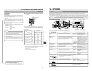
ADJUSTMENT OF LENS IRIS
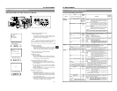
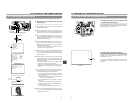
The lens iris can be adjusted using any of the
following three methods.
• Automatic adjustment
Set the iris mode switch to "A" (Auto).
The iris is adjusted automatically according to the brightness
of the object.
• Manual adjustment
Set the iris mode switch to "M" (Manual).
The iris can be adjusted manually by rotating the iris ring.
• Temporary auto iris adjustment
During manual iris adjustment, the auto iris adjustment mode
is activated only while this button is held depressed.
Ⅲ Changing the auto iris adjustment setup
Under special lighting conditions such as backlight, it is often
appropriate to change the value set by the auto iris
adjustment.
This can be done by the following methods.
• Setting the AUTO IRIS LEVEL switch of the camera
☞ See "SWITCH FUNCTIONS" on page 90.
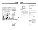
ZEBRA PATTERN DISPLAY DURING MANUAL ADJUSTMENT
13-2 IRIS (Brightness) Adjustment
AUTO
WHITE
SKIN
AREA
ACCU
FOCUS
TAKE
VTR
PUSH
ZEBRA
AUDIO
LEVEL CH-1
ON
OFF
ZEBRA switch
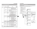
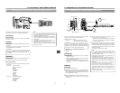
By setting the ZEBRA switch to ON, oblique stripes (zebra
pattern) can be displayed in the sections with a luminance level
of 70% to 80% or sections with levels over 100% in the
viewfinder.
The zebra pattern can be used as a reference for manual iris
adjustment.
When adjusting the iris manually, adjust it so that the zebra
patterns are displayed in the section that you want to stress in
the subject.
• When CHARACTER of the Camera SETUP Menu screen is
set to ON, the zebra pattern will also appear in the MONITOR
OUT connector video.
• The zebra pattern will also appear during color bar output
when the ZEBRA switch is set to ON.
• The initial setting is 70 to 80%. However, using the "ZEBRA"
setting on the VF DISPLAY MENU, zebra patterns can be
displayed in the sections with a luminance level of 85% to
95%, over 95% and over 100%.
☞ See "VF DISPLAY MENU Screen" on page 78.


