


24
4. CONNECTIONS
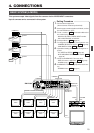
REAR PANEL CONNECTORS (Continued)
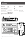
DATA I/O
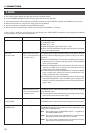
Ⅵ ALARM INPUTS 1 to 16
TTL level (Make/Break), input duration 70 ms or more.
REF. : “CONTROL UNIT SCREEN” on page 28 and
“POLARITY item of DATA I/O SCREEN (INPUT
ASSIGNMENT SCREEN)” on page 31 for the Make/
Break switching.
Ⅵ ALARM/SELECT OUTPUTS 1 to 16
Alarm or selection output.
Open-collector output of a LOW pulse for between 500 ms
and 1000 ms.
Max. voltage 30 V, current 30 mA.
Ⅵ UNIT ALARM
Open-collector, LOW output during the alarm time period.
Maximum voltage, 30 V, current 30 mA.
Ⅵ CAM SW
● Connect to the CAM SW OUT (camera switching signal
output) terminal of the time-lapse VCR. Time-lapse re-
cording is not available if this connection is not made.
● Set “polarity” according to the VCR to be used. When
using a JVC time-lapse VCR, set to “LOW”.
REF. : “CONTROL UNIT SCREEN” on page 28 and “CAM
SWITCH item of DATA I/O SCREEN” on page 30.
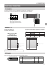
REF. : “DATA I/O SCREEN” on page 30 for the input/output signal switching.
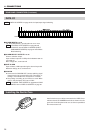
DATA I / O
COM
1 2 3 4 5 6 7 8
COM
9/19/1 10/210/2 11/311/3 12/412/4 13/513/5 14/614/6 15/715/7 16/816/8
COM COM COM
CAMERA
SWSW
UNIT
ALARMALARM
AUTO
HOLD
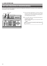
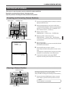
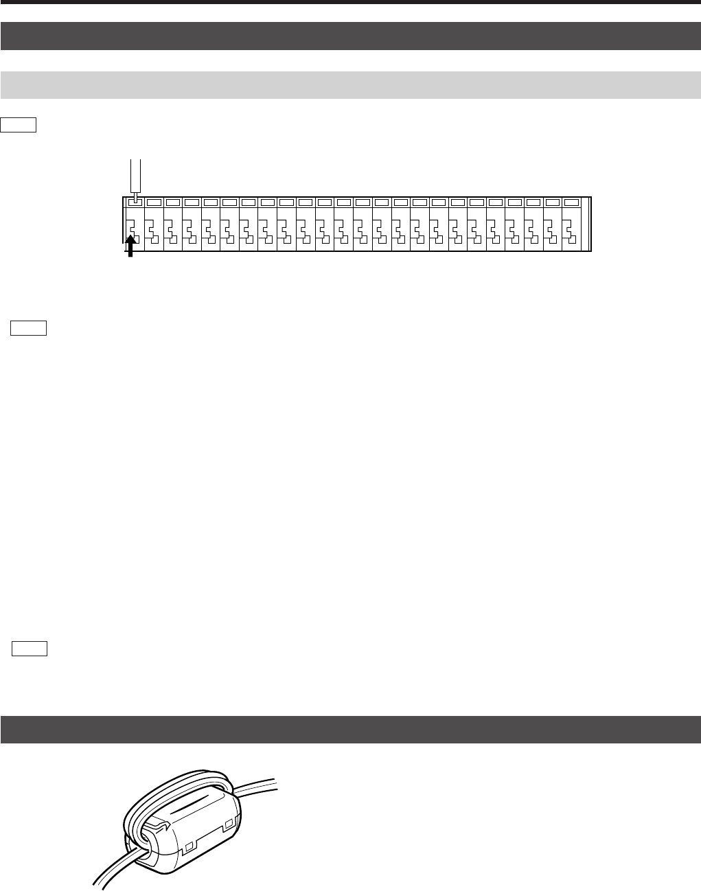
Install a ferrite core on cables connected to the DATA I/O ter-
minals and to the TO CAMERA terminals as shown in the dia-
gram on the left. Keep the ferrite core as close as possible to
the remote control unit.
Installing the Ferrite Core