


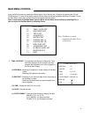
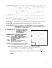
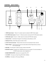
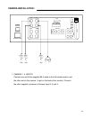
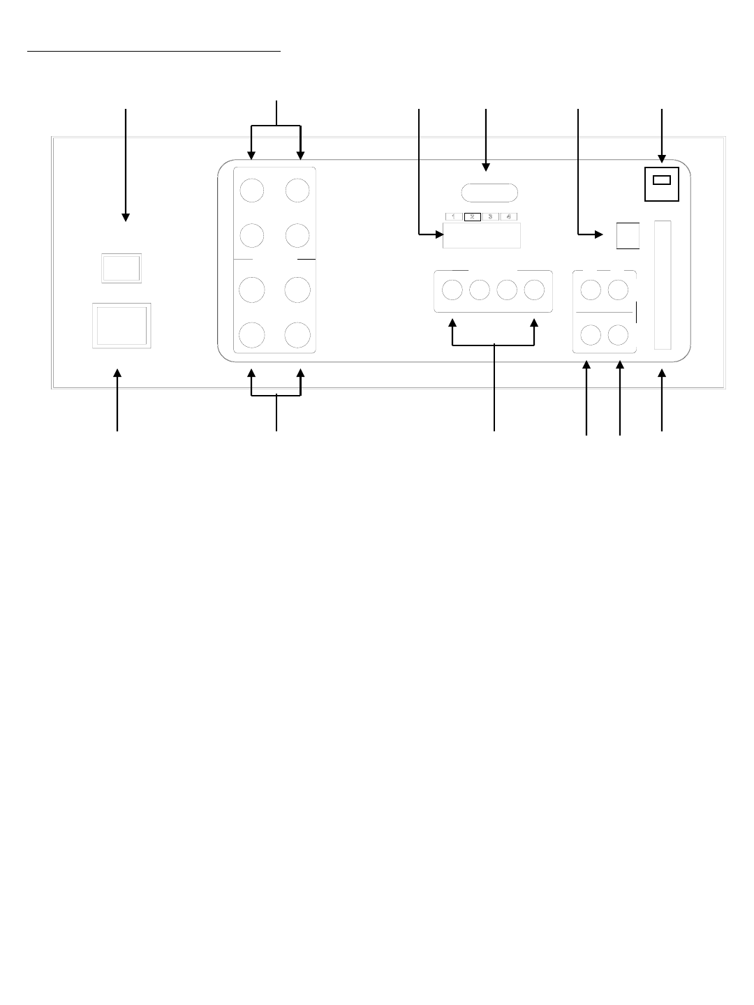
CONTROL - BACK PANEL :
10 2 6 9 7 12
AUDIO
SLAVE
OUT
4
VIDEO
MONITOR
OUT
IDE-SUB
USB
+ -
SENSOR INPUT SENSOR
OUTPUT
AC100-240V,50/60Hz
AC INPUT
POWER
MAIN S/W
CH4CH2
VIDEO INPUT
CH2 CH4
CH1 CH3
+ -
1 23
+ -
AUDIO INPUT
+ - + -
CH1 CH3
RS-232
11 1 3 4 5 8
1. BNC Camera Inputs - Channel 1-4 camera inputs (for cameras with BNC Video outputs)
2. 6 Pin DIN Camera Inputs - Channel 1-4 Camera inputs (for cameras with 6 Pin DIN camera outputs).
3. RCA Audio inputs - Channel 1-4 Audio inputs (for cameras with RCA Audio outputs)
4. Slave A/V Out - Audio/Video Out signal for transmitting to a Slave Monitor or VCR.
5. Monitor A/V Out - Audio/Video output to another monitor.
6. Alarm Function Terminals - These terminals are used to connect external motion sensors.
7. Sensor Output - These terminals are used to connect external Alarm Output devices, such as a
siren or security light.
8. IDE-SUB - This connector is used to connect an external Slave HDD.
9. RS-232C Terminal - Connects to the RS-232C terminal on your computer. For more information on
RS-232C communication, refer to Appendix #4.
10. MAIN POWER SWITCH - Used to turn the system ON or OFF.
11. AC INPUT – Connects to a Power Plug (AC100-240V, 50/60Hz).
12. USB Port – Connects to a PC using a USB cable
-16-
USB