© National Instruments Corporation 2-1 NI 17xx Smart Camera User Manual
2
Power and I/O
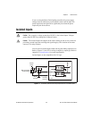
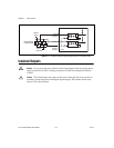
This chapter provides information about the NI Smart Camera
POWER-I/O connector, connecting isolated inputs and isolated outputs,
and connecting to serial devices and to quadrature encoders.
POWER-I/O Connector
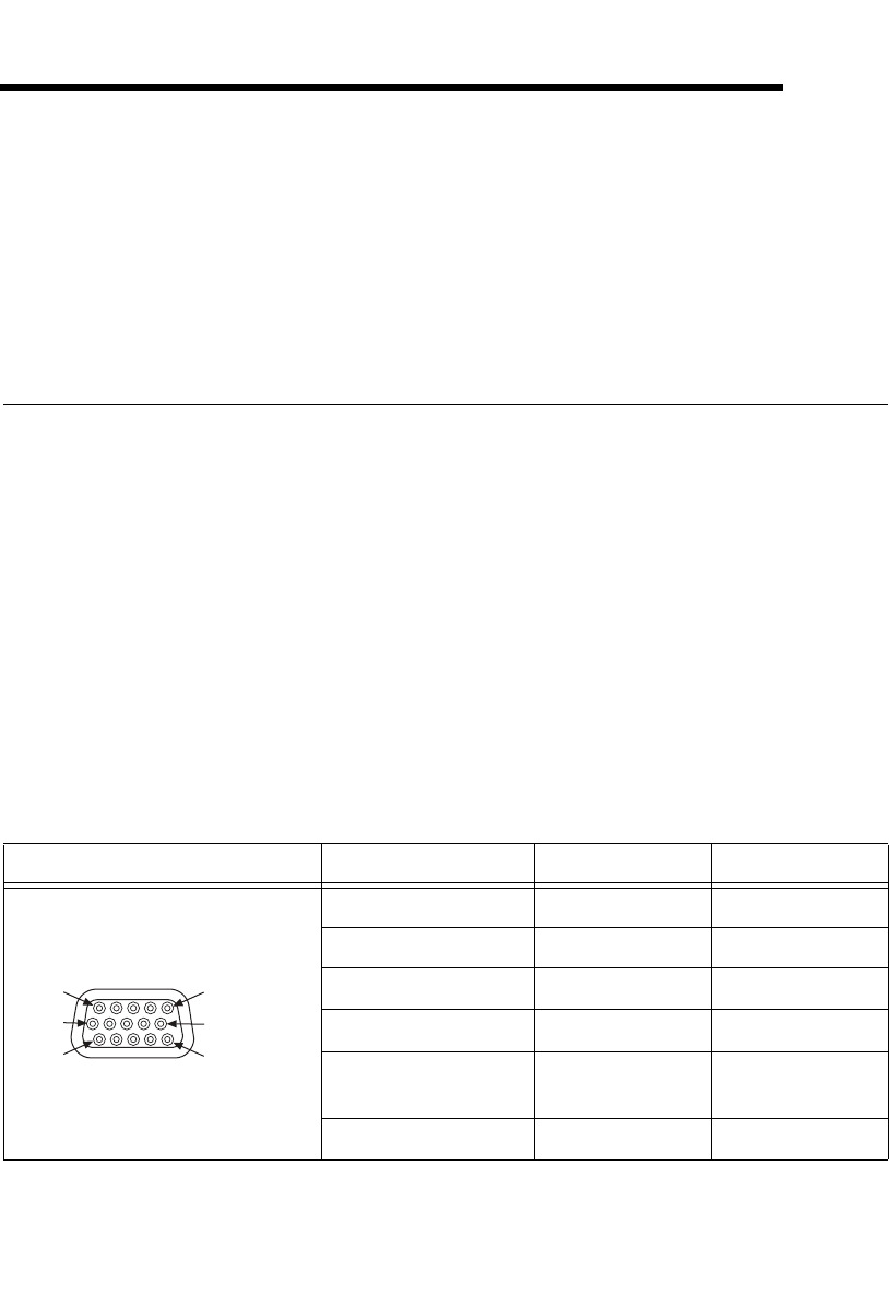
The POWER-I/O connector provides signal connections for power and I/O,
including isolated inputs and outputs, quadrature encoders, and serial
devices. The POWER-I/O connector is a standard female high-density
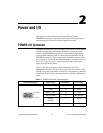
15-pin D-SUB connector. Table 2-1 shows the pin organization for the
POWER-I/O connector. The two pins used to connect to a power supply,
pin 15 and pin 5, are also shown in the table. Refer to Getting Started with
the NI 17xx Smart Camera for information about connecting a power
supply to the NI Smart Camera.
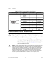
Table 2-1 lists the signal names and pin numbers for the 15-pin
POWER-I/O connector. The table also lists the wire colors for the 15-pin
D-SUB pigtail cable (part number 197818-05), sold separately by National
Instruments. Cables sold by other manufacturers could have different wire
colors.
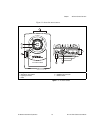
Table 2-1. POWER-I/O Connector Signal Descriptions
Connector Diagram Signal Name Pin Number Wire Color
+24 V 5 Red
COM 15 Black
RS232_TXD 10 Pink
RS232_RXD 14 Black/White
TrigIn+
IsoIn(0)+
2 Brown
IsoIn(1)+ 8 Orange
5 (+24 V)
15 (COM)
11
6
1
10


