


Chapter 5 Image Acquisition
© National Instruments Corporation 5-5 NI 17xx Smart Camera User Manual
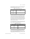
The incoming trigger is synchronized to the line rate of the smart camera.
This adds an additional delay that can vary on a frame by frame basis.
The maximum variability is shown in Table 5-1.
The amount of time required from the assertion of a trigger to the start of
the light strobe and image exposure varies by application. For example, if
a sensor that detects the presence of a part is positioned before the smart
camera on a conveyor belt, a trigger delay will be necessary so that the
smart camera waits to expose the image until the part to be inspected passes
in front of the smart camera. In this case, specifying the trigger delay in
terms of quadrature encoder counts allows the smart camera to expose the
image when the part is positioned in front of the smart camera regardless of
changes in speed of the conveyor belt. For other applications, a delay
specified in milliseconds is sufficient.
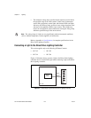
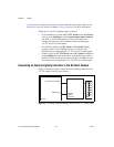
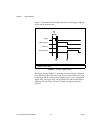
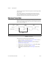
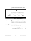
If you are strobing a light, there is a short delay while the lighting controller
turns on the light. This delay is represented by the lighting turn-on time in
Figure 5-1. Table 5-2 lists the lighting turn-on times.
After the lighting turn-on time, the exposure begins. The width of the
exposure pulse determines how long the sensor is exposed. The exposure
time can be adjusted by setting the Exposure Time control in Vision
Builder AI, setting the Exposure Time property in LabVIEW, or by setting
the Exposure Time control in MAX. The lighting strobe deasserts at the
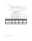
Table 5-1. Trigger Synchronization Variability
Smart Camera Model Trigger Synchronization Variability
NI 1722
NI 1742
NI 1762
31.2 μs
NI 1744
NI 1764
71.6 μs
Table 5-2. Lighting Turn-On Time
Smart Camera Model Lighting Turn-On Time
NI 1722
NI 1742
NI 1762
156 μs
NI 1744
NI 1764
143.2 μs