Chapter 4 Lighting
NI 17xx Smart Camera User Manual 4-8 ni.com
cycle that do not violate the limits of the external controller and/or light(s). Refer to the
Maximum Frame Rate section of Chapter 5, Image Acquisition, for more information.
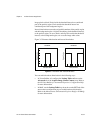
Enable the 5 V and 24 V lighting outputs as follows:
• In Vision Builder AI, enable the 5 V TTL Strobe and/or 24 V Strobe
controls on the Lighting tab of the Acquire Image (Smart Camera)
step. Refer to the NI Vision Builder for Automated Inspection:
Configuration Help for more information about configuring the
5 V TTL and 24 V strobe outputs.
• In LabVIEW, configure the 24V Strobe and 5V Strobe lighting
properties. Refer to the NI-IMAQ VI Reference Help for more
information about configuring the 5 V TTL and 24 V strobe outputs.
• In MAX, select the 5 V TTL Strobe and/or 24 V Strobe checkboxes
on the Lighting tab of the smart camera configuration page. Refer to
the Measurement & Automation Explorer Help for NI-IMAQ for more
information about configuring the 5 V TTL and 24 V strobe outputs.
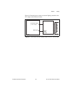
Connecting an External Lighting Controller to the NI Smart Camera
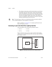
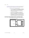
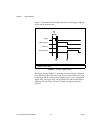
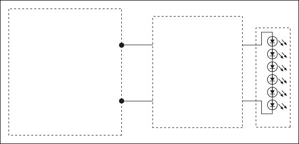
Figure 4-3 illustrates how to connect an external lighting controller to the
5 V TTL output on the NI Smart Camera.
Figure 4-3. Connecting an External Lighting Controller to the 5 V TTL Strobe Output
5 V TTL Strobe Output
GND Output
LED
External
Lighting
Controller
NI 17xx


