


1312
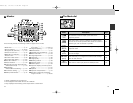
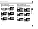
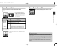
16
15
14
13
12
A
11
10
9
17
18
B
19
20
21
22
23
24
25
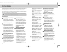
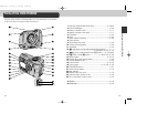
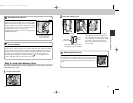
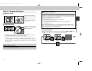
1 Red-eye reduction/Self-timer lamp .............................p. 48/42
2 Built-in Speedlight ...........................................................p. 48
3 Battery chamber cover....................................................p. 17
4 Battery chamber cover latch............................................p. 17
5 Viewfinder........................................................................p. 26
6 Lens ..............................................................................p. 144
7 Video output connector ...................................................p. 68
8 Tripod socket
9 Flash-ready lamp (red) .....................................................p. 28
10 Autofocus lamp (green)....................................................p. 28
11 Viewfinder........................................................................p. 26
12 1 (exposure compensation/sensitivity)/5 button..................
.....................................................p. 51/53/32, 33, 52, 57, 58
13 2 (focus mode/manual focus)/6 button......p. 41/54/63
14 3 (flash mode)/7 button ...................p. 49/32, 33, 57, 58
15 MENU button ............................................................p. 34, 76
16 QUICK p (quick review) button .....................................p. 30
17 Shutter release button .....................................................p. 28
18 Power switch.............................................................p. 24, 29
19 Zoom button .................................................p. 26, 46, 57, 59
20 TRANSFER button...........................................................p. 67
21 Camera strap eyelet ........................................................p. 16
22 Multi selector
23 Memory card slot cover...................................................p. 19
24 USB connector (under cover) ..........................................p. 66
25 DC-in connector (under cover).........................................p. 18
A Monitor ...........................................................................p. 14
B Mode dial........................................................................p. 15
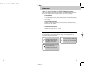
Introduction—Parts of the COOLPIX4300
4
3
2
1
5
6
7
8
The parts of the camera are identified below. For more information on the function
of each part, refer to the page number that follows it.
Parts of the COOLPIX4300
E4300 (E) 02.12.9 1:46 PM Page 12