


13
9
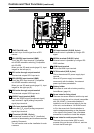
5($57$//<6UHG
Can be lit by a control signal from a GPI/
camera.
10
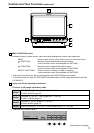
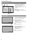
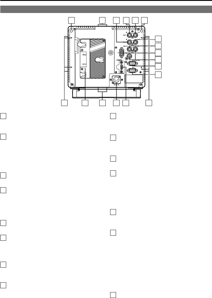
6',+'6'LQSXWWHUPLQDO%1&
This is the SDI1 input terminal. (Compatible
with HD/SD automatic switching, Compatible
with 3G-SDI)
When you use 3D assist mode (page 51), input
images for the left eye (L).
11
6',DFWLYHWKURXJKRXWSXWWHUPLQDO
This terminal outputs SDI1 input as is.
12
6',+'6'LQSXWWHUPLQDO%1&
This is the SDI2 input terminal. (Compatible
with HD/SD automatic switching)
When you use 3D assist mode (page 51), input
images for the right eye (R).
13
6',DFWLYHWKURXJKRXWSXWWHUPLQDO
This terminal outputs SDI2 input as is.
14
9,'(2<LQSXWWHUPLQDO%1&
This is the VIDEO signal (component signal)
input terminal/Y signal (analog component
signal) input terminal.
15
P
B
/P
R
LQSXWWHUPLQDO%1&
This is the P
B
/P
R
signal (analog component
signal) input terminal.
16
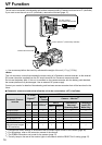
9)WHUPLQDO'68%SLQV
This terminal connects to the VF (viewfinder)
terminal of broadcasting and business cameras
made by Panasonic.
The unit can be used as the viewfinder for such
a camera.
17
*3,LQSXWWHUPLQDO'68%SLQV
External control is possible by using a GPI
signal.
18
6(5,$/WHUPLQDO'68%SLQV
External control is possible by using an RS-
232C interface.
19
+'0,LQSXWWHUPLQDO
This is the HDMI input terminal.
20
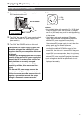
'&,1WHUPLQDO;/5SLQV
This is the external DC power supply input
terminal.
When a DC power supply is connected
concurrently with the battery, the external
power input takes precedence.
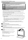
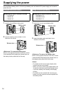
21
%DWWHU\KROGHU
This holder is used with a battery made by
Anton/Bauer. (page 14)
22
6FUHZKROHVIRUIL[LQJWULSRG
There are two screw holes on both the top and
bottom for fixing the unit to a tripod (compatible
with 3/8-16UNC). A removable adapter is
installed in one of the screw holes on the top
of the unit, and enables a 1/4-20UNC screw
to fit in the screw hole. Decide whether to
use the adapter depending on the diameter
of the tripod’s fixing screw. Use a flat-blade
screwdriver to remove or install the adapter.
23
6FUHZKROHVIRUPXOWLSXUSRVHIL[LQJ
There are four screw holes (M3) for multi-
purpose fixing on the rear of the unit, and two
on each the left and right.
&RQWUROVDQG7KHLU)XQFWLRQV
FRQWLQXHG
Rear panel
1112 10
9
22
1921 2023 23
13
14
15
16
17
18
22
9