


English _21
● INSTALLATION & CONNECTION
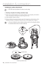
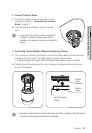
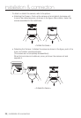
installation & connection
`
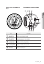
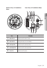
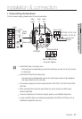
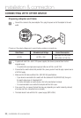
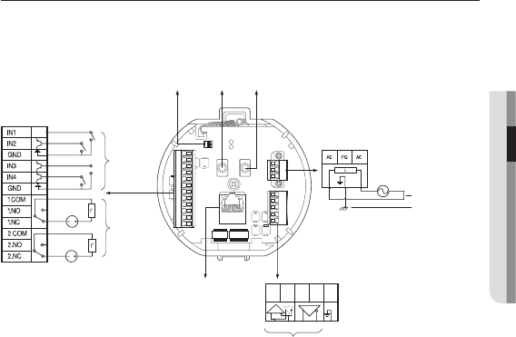
Camera Wiring Interface Board
For the camera wiring, please refer to the picture below.
J
`
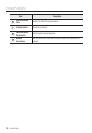
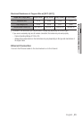
Select Normal Open in the setup menu.
-
The sensor input is activated during a short for contact type, or when it is at “Low” level for
the active type.
`
Select Normal Close from the Setup menu.
-
The sensor input is activated when open for the contact type or when in high impedance
state (open collector) for the active type.
`
The maximum capacity of the alarm output terminal is 30V DC/2A, 125V AC/0.5A and 250V
AC/0.25A.
`
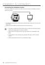
When connecting alarm input and output cables, be sure to connect one cable to each
terminal respectively.
`
To connect products over the camera’s capacity, please use an additional relay device.
`
If power and GND cables are connected inappropriately to the NC/NO or COM port, a fire or
breakdown of equipment may occur.
AC- FG AC-
AUDIO OUT
AUDIO IN
GND
1.COM
1.NO 1.NCIN1 IN2 GND IN3 IN4
2.COM
2.NO
2.NC
D+ D- TXD+ TXD-GND
D+ D- TXD+ TXD- GND
ETHERNET
Refer to Control Signal
Connection Diagram
Audio
IN
Video
Output
Audio
OUT
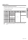
(SNP-5430 : AC 24V, 2.5A/
SNP-5430H : AC 24V, 3A)
Power Input
Ground
Power Supply
Communications
Alarm output
Alarm
Input
Alarm