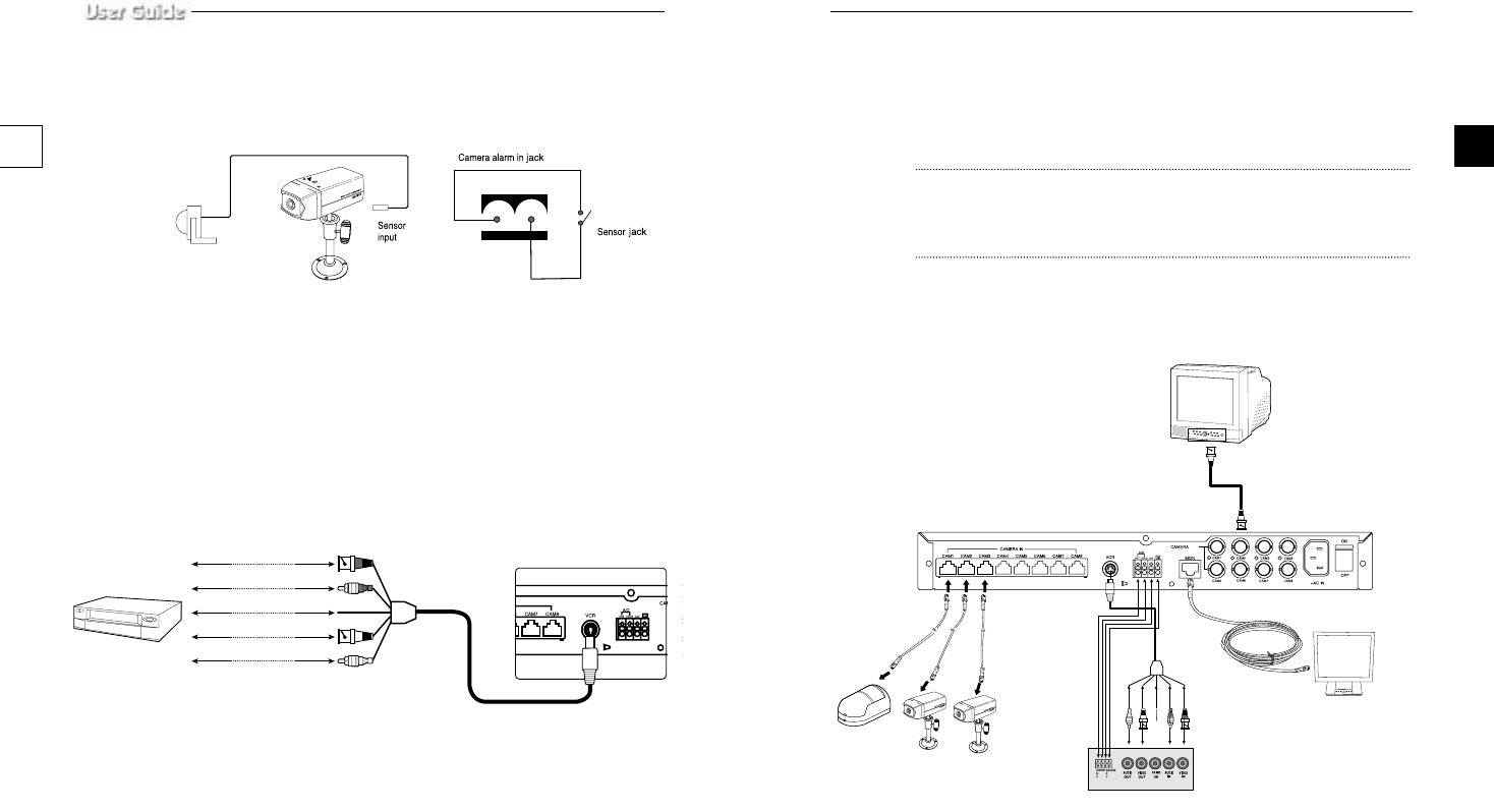
f) Connect the A/O (HOT) terminal on the rear panel to the Alarm IN terminal of the VCR.
g) Connect the A/O (COLD) terminal on the rear panel to the Ground terminal of the VCR.
h) Connect the A/R terminal on the rear panel to the Alarm Reset terminal of the VCR.
i) Connect the G (ground) terminal on the rear panel to the Ground terminal of the VCR.
Caution
This Kit is composed of one monitor and three Camera at the Shipping. But this System can
accommodate 8 cameras. So you can buy Cameras Supplementally and add those to the
system.
1-6) Whole System connection and configuration
e-23e-22
OUT
VCR (TIME LAPSE) REAR
TFT-LCD MONITOR
DUAL QUAD BOX
1-5) External terminal connecting method for CAMERA and
SYSTEM
1) External terminal connecting method for CAMERA
•
An additional PIR sensor or external sensor can also be connected.
•
The additional PIR sensor can be connected as shown in the above graphic.
•
Sensor’s trigger signal is NO (Normal Open).
•
Sensor is not supplied. (Sold separately)
2) VIDEO OUT BNC (1~8) terminals connecting method of Quad rear
VIDEO OUT BNC1 ~ BNC8 terminals in the rear of the Quad are VIDEO terminals for outputting
video images from OBSERVATION CAMERA to THROUGH OUT.
BNC VIDEO output terminal can be used to connect to VCR (TIME LAPSE) or SLAVE MONITOR.
3) VCR or ALARM terminal connecting method
a) Connect the 6-pin plug to the VCR terminal on the rear panel.
b) Connect the VIDEO OUT plug to the VIDEO IN terminal of the VCR.
c) Connect the VIDEO IN plug to the VIDEO OUT terminal of the VCR.
d) Connect the AUDIO OUT plug to the AUDIO IN terminal of the VCR.
e) Connect the AUDIO IN plug to the AUDIO OUT terminal of the VCR.
VIDEO IN
TIME LAPSE VCR
OR NORMAL VCR
VIDEO OUT
AUDIO IN AUDIO OUT
VIDEO OUT VIDEO IN
AUDIO OUT AUDIO IN
NOT USED TRIGGER
00403A SSC-17TQ_ENG 10/9/03 11:30 AM Page e-22


