


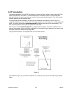

f
= The focal length of the imaging optic at the wavelength of the laser.
If you are not already versed in the theory behind the Focal Length method, we recommend the
following reference document:
Laser Far-Field Beam-Profile Measurements by the Focal Plane Technique
, by G.W. Day and C.F.
Stubenrauch, NBS Technical Note 1001, March 1978. This publication is no longer in print. A copy
can be obtained from the Spiricon Sales or Service department.
6.21.2 The Far-Field Method
This method is based upon the actual measured increase in laser beam width as it expands in the far-
field region. Before using this method, be sure that your measurements will be made in the beam’s
far-field region, and the size of the beam does not grow larger than your camera’s ability to contain it.
Divergence results will be computed in the X and Y aligned axes of the beam if Elliptical results are
disabled, or for Major and Minor axes beam orientations if Elliptical results are enabled.
Notice: We strongly recommend that you do not use the Elliptical mode when using the Far-Field method,
but rather rotate your camera to bring the axes of the laser into X and Y alignment.
Position the camera in the beam path to acquire a first, or Reference, beam width. It is assumed
that this first sample will be the one nearest the beam waist, and thus the smaller sample width.
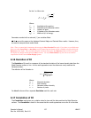
Next, move the camera a distance further from the beam waist. Note the distance the camera has
traveled as the Separation distance. The Divergence result is computed as follows:
divergence
WW
S
CR
=⋅
−
⋅
−
2
2
1
tan
Where:
W
R
= The width of the beam at the Reference (nearer to the waist) location.
W
C
= The width of the beam at the Current (further from the waist) location.
S
= The separation distance between the two beam width sample locations.
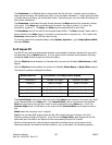
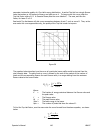
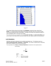
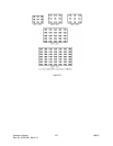
6.22 Histogram
The LBA-PC can produce a fluence Histogram of the currently displayed frame of data. Each bar in
the display represents a fluence Bucket. Each Bucket describes a range of quantized fluence values.
The minimum Bucket Size is based upon a single count of the digitized output of the A to D converter.
The Bucket will be scaled if energy calibration is in use. With energy calibration in effect, the raw
values are simply multiplied by a scaling factor that converts them to energy densities. For simplicity,
all of the following discussions will assume no
energy
calibration. Thus, a raw A to D pixel intensity
range of from 0 to 255/1023/4095/16383/32767 will be assumed.
Image processing can alter the numerical value of a pixel’s intensity. Ultracal, Reference Subtraction,
Frame Averaging and Frame Summing are all processes that transform the simple 8/10/12/14/15 bit
integer input from the A/D conversion, into a signed 16 bit fixed point value. For ease of use, we have
forced all buckets to be defined in raw pixel integers. Thus a Bucket size of 4, starting at zero, will
contain the intensity values from 0 to 3.992, the next bucket goes from 4 to 7.992, and so on.
Operator’s Manual LBA-PC
142