


by 256 rows of video and then 20 rows of black, try a first value of 18 (24-6) for Vertical
Start. If your camera is interlaced, and each frame outputs a total of 525 rows (i.e. 262.5
rows per field), and the first 32 rows of each frame are black, followed by 490 rows of video
per frame, try a first value of 20 (32-12) for Vertical Start.
7.3.4 Vertical Size
This value must always be an even number: Enter the number of rows that contain video
data. In the above Vertical Start examples set this value to 256 in the first example, and 490
for the second example. Before the release of software version 4.xx, this value was limited to
a maximum of 1000 rows. After version 4.xx this value maximum is 2000 rows. It is a good
idea to start with a value 50 to 80% less than the maximum for your camera and then work
up to a number that the frame grabber can actually support. This is particularly important for
mega-pixel style cameras.
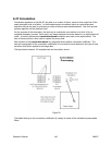
7.3.5 Horizontal Start
This value must be an even number. Enter the pixel clock where the video data begins. A
good starting value is approximately half the number of clocks from the end of HSYNC. For
example: Suppose the first active pixel is 25 PCLK’s after the end of HSYNC. Enter a first
value of 12 for Horizontal Start.
7.3.6 Horizontal Size
This value must be an even number. Enter the number of active pixels in each horizontal
row. Before the release of LBA software version 4.xx, this value was limited to a maximum of
1000 pixels. After version 4.xx this value maximum is 2000 pixels. It is a good idea to start
with a value 50 to 80% less than the maximum for your camera and then work up to a
number that the frame grabber can actually support. This is particularly important for mega-
pixel style cameras with high-speed pixel clocks. Pixel clock frequencies below 15MHz will
allow large mega-pixel cameras to interface with the largest image sizes. Cameras with high
clock frequencies will require a reduction of the image size that can be acquired. We have
successfully interfaced cameras with clock rates at 25MHz, but with a loss in image width.
This will vary from camera to camera depending upon how the image is formatted.
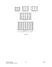
After making the above settings click Start! and see if you are able to acquire some data
frames. At this point, it is best to operate in Continuous capture and CW trigger mode. Also
make sure that your Zoom setting is indicating X1 resolution and the Lens check box is not
checked. If the above guesses were close, you should be acquiring data frames. If not, then
further reduce the Vertical Start and Horizontal Start values until data frames are
collected.
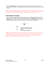
With your camera detector illuminated you should see the boundary of two sides of your
camera’s detector, that is unless one or both of the above guesses turn out to be exactly
correct. The next step is to adjust the Vertical Start and Horizontal Start values such that
the camera image is set to just fill the acquired data window. Note: It is not a necessity that
you configure the capture width and height to acquire all the data output by your camera. If
you only want to input a portion of the detector you can reduce the Vertical Size and
Horizontal Size to smaller values.
Operator’s Manual LBA-PC
Doc. No. 10654-001, Rev 4.10
153