


Overview
Location and Function of Parts
16
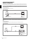
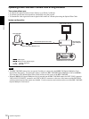
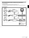
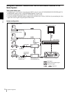
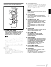
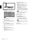
M VISCA RS-232C IN connector
Connect to the RM-BR300 Remote Control Unit
(not supplied). When you connect multiple
cameras, connect it to the VISCA RS-232C OUT
connector of the previous camera in the daisy chain
connection.
N VISCA RS-232C OUT connector
When you connect multiple cameras, connect it to
the VISCA RS-232C IN connector of the next
camera in the daisy chain connection.
O DC IN 12V connector
Connect the supplied AC power adaptor.
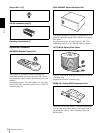
P Card slot
Insert an optional interface card such as BRBK-
301, BRBK-302 and BRBK-303.
The slot cover is attached to the camera at the
factory.
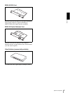
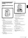
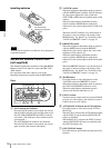
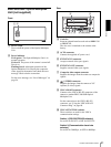
Bottom
Q Ceiling bracket mounting screw holes
When you install the camera to the ceiling, secure
the supplied ceiling bracket to these holes using the
supplied four screws.
For installation, see “Installing the Camera on the
Ceiling” on page 43.
R Tripod screw holes (1/4-20UNC)
When you install the camera to a tripod, secure the
tripod to these holes.
S BOTTOM switches
Used for the RS-232C/RS-422 selection, baud rate
selection, remote control signal output on/off and
camera address setting.
For details, see “Setting of the BOTTOM switches”
on page 16.
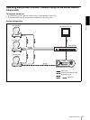
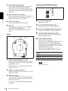
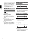
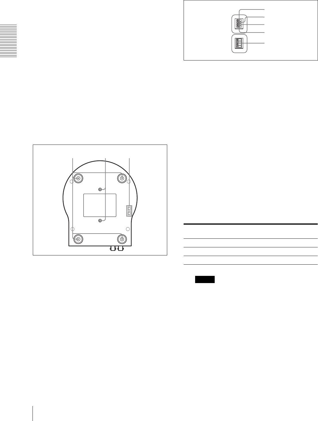
Setting of the BOTTOM switches
1 Switch 1 (No Connection)
Always keep it OFF.
2 Switch 2 (RS-232C/RS-422 selector)
Set to ON for RS-422, or OFF for RS-232C.
3 Switch 3 (Communication baud rate selector)
Set to ON for 38400bps, or OFF for 9600bps.
4 Switch 4 (Infrared signal output switch)
Set to ON to enable an infrared signal output, or
OFF to disable the output.
5 Camera address selectors
Set the address of the camera.
Normally set to "0". With this setting, addresses are
assigned to the cameras automatically in the
connected order by pressing the POWER button
while holding down the RESET button on the RM-
BR300 Remote Control Unit.
You can assign the camera address "1" to "7"
manually by setting these selectors as follows:
Note
Switch 4 is not used.
qkqj ql
Camera
address
01234567
Switch 1 OFF ON OFF ON OFF ON OFF ON
Switch 2 OFF OFF ON ON OFF OFF ON ON
Switch 3 OFF OFF OFF OFF ON ON ON ON
O
N
1
2
3
4
O
N
1
2
3
4
2
1
4
5
3