


Overview
Location and Function of Parts
21
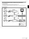
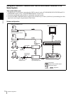
BRU-300/300P Optical Multiplex
Unit (not supplied)
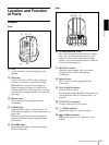
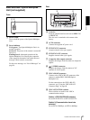
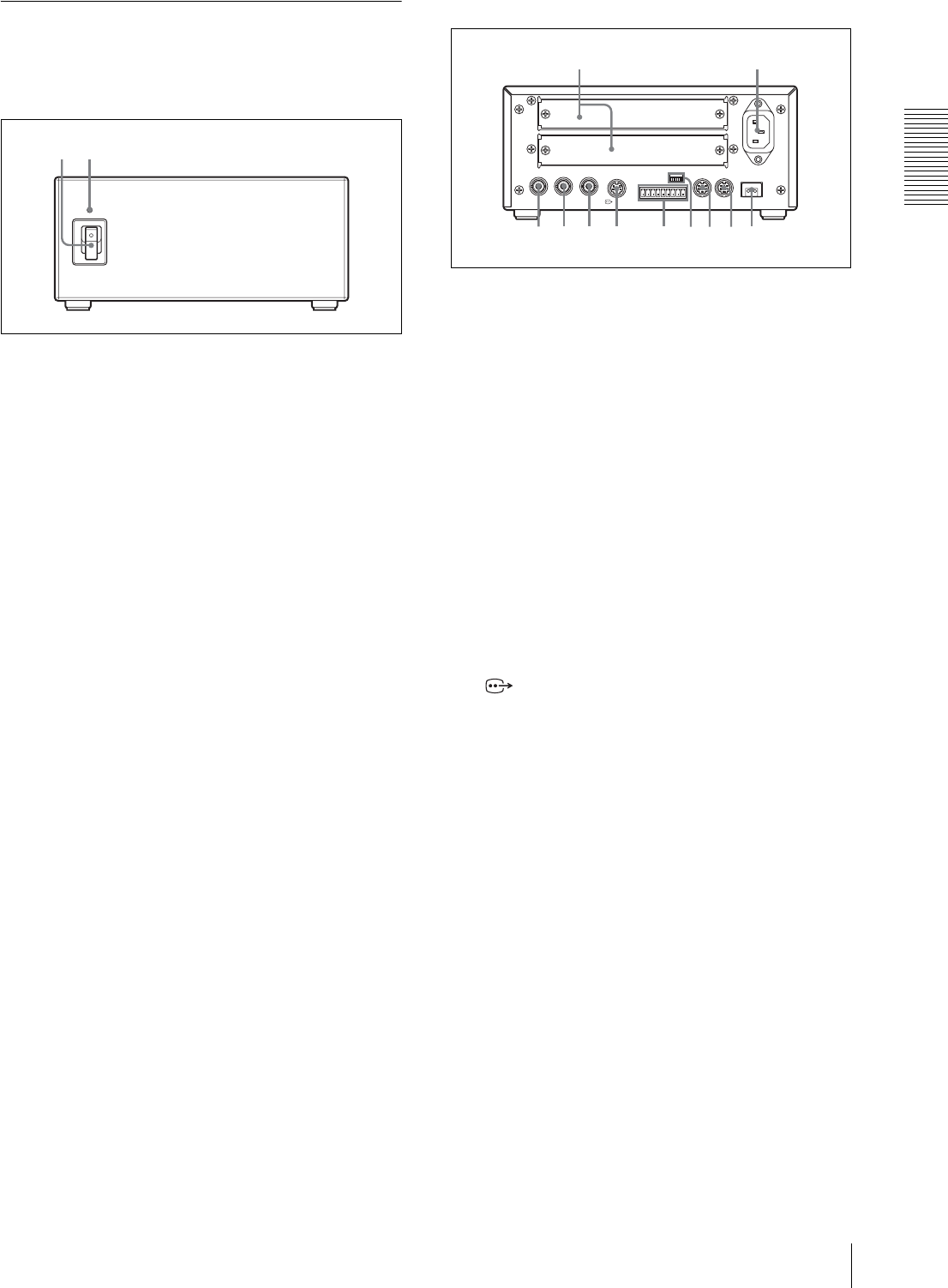
Front
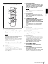
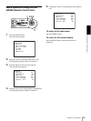
A Power switch
Turns on/off the power of the Optical Multiplex
Unit.
B Power indicator
Lit in green: The Optical Multiplex Unit is in
normal operation.
Lit in red: The power of the camera is turned off.
Turn it on.
Flashing in red: Abnormal operation of the
Optical Multiplex Unit. Display the composite
video signal on the monitor and check the error
message. Check also the connection.
For the error message, see “List of Messages” on
page 54.
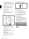
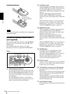
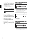
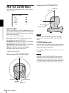
Rear
C Card slot
Insert an optional interface card such as BRBK-301
or BRBK-302.
The slot cover is attached to the camera at the
factory.
D AC IN connector
Connect the supplied AC power cord.
E EXT SYNC IN connector
Accepts external video sync signals.
F EXT SYNC OUT connector
Supplies external video sync signals.
G Composite video output connector
Supplies the images from the camera as composite
signals.
H S VIDEO connector
Supplies the images from the camera as Y/C
separate (S video) signals.
I VISCA RS-422 connector
Connect to the VISCA RS-422 connector of the
camera or another BRU-300/300P Optical
Multiplex Unit.
For the connection to the VISCA RS-422
connector, see “Using the VISCA RS-422
Connector Plug” on page 68.
J VISCA FUNCTION switches
These switches are used for the VISCA
communication settings.
Switch 1 (RS-232C/RS-422 selector)
Set to ON for RS-422, or OFF for RS-232C.
Switch 2 (Communication baud rate
selector)
Set to ON for 38400bps, or OFF for 9600bps.
21
IN EXT SYNC OUT
S VIDEO
VISCA RS-232C CAMERA
~
AC IN
IN OUT
VISCA RS-422
FUNCTION
1
6
5 6
34
7 8 q
d
q
a
q
s
09