


Installation and Connections
Connections
51
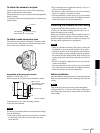
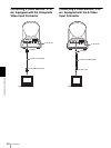
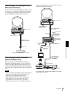
Connecting a VTR Equipped with
SDI Input Connector
When you install an optional BRBK-302 SDI Card into
the camera, you can output the signal from the camera
by converting it into a signal compliant with the SDI
standard (SMPTE 259M serial digital interface).
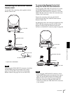
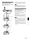
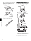
Connecting the BRU-300/300P
Optical Multiplex Unit
When you install an optional BRBK-303 Optical
Multiplex Card into the camera, you can connect the
camera to the BRU-300/300P Optical Multiplex Unit
using the CCFC-M100 Optical Fiber Cable. This allows
you to control the camera from up to 500 m (1,640 feet)
away.
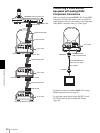
Notes
• When the connection using the Optical Fiber Cable is
made, the VISCA RS-232C and VISCA RS-422
connectors on the camera cannot be used.
• When using the VISCA RS-232C connectors or
VISCA RS-422 connectors, check the VISCA
FUNCTION switch on the rear of the Optical
Multiplex Unit (page 21) and the DIP switch on the
bottom of the Remote Control Unit (page 20) are set
to RS-232C or RS-422 correctly.
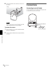
EXT SYNC IN
IR SELECT
75
1 2 3
OFF ON
IN VISCA RS-232C OUT
!
VISCA RS-422
1 2 3 4 5 6 7 8 9
DC IN
12V
R
VIDEO S VIDEO
SDI
to AC outlet
BRBK-302 SDI Card
Connecting cable
with BNC connectors
to SDI input
DVCAM, etc. equipped with an SDI input
EXT SYNC IN
IR SELECT
75
1 2 3
OFF ON
IN VISCA RS-232C OUT
!
VISCA RS-422
1 2 3 4 5 6 7 8 9
DC IN
12V
R
VIDEO S VIDEO
to AC outlet
BRBK-303 Optical
Multiplex Card
AC power cord
(supplied with the
BRU-300/300P)
CCFC-M100 Optical
Fiber Cable
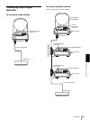
VISCA RS-232C IN
to AC outlet
CAMERA
BRU-300/300P
Optical Multiplex
Unit
to T VIDEO
(or S VIDEO)
75-ohm coaxial
cable (or S-
video cable)
Video monitor, etc.
RS-232C cable
(supplied with the
RM-BR300)*
VISCA RS-232C
RM-BR300 Remote Control Unit
to AC outlet
* The VISCA RS-422 connection is also available if you use the
VISCA RS-422 connectors.