


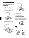
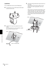
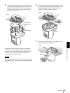
Installation and Connections
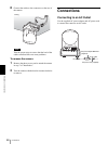
Connections
50
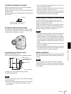
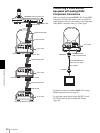
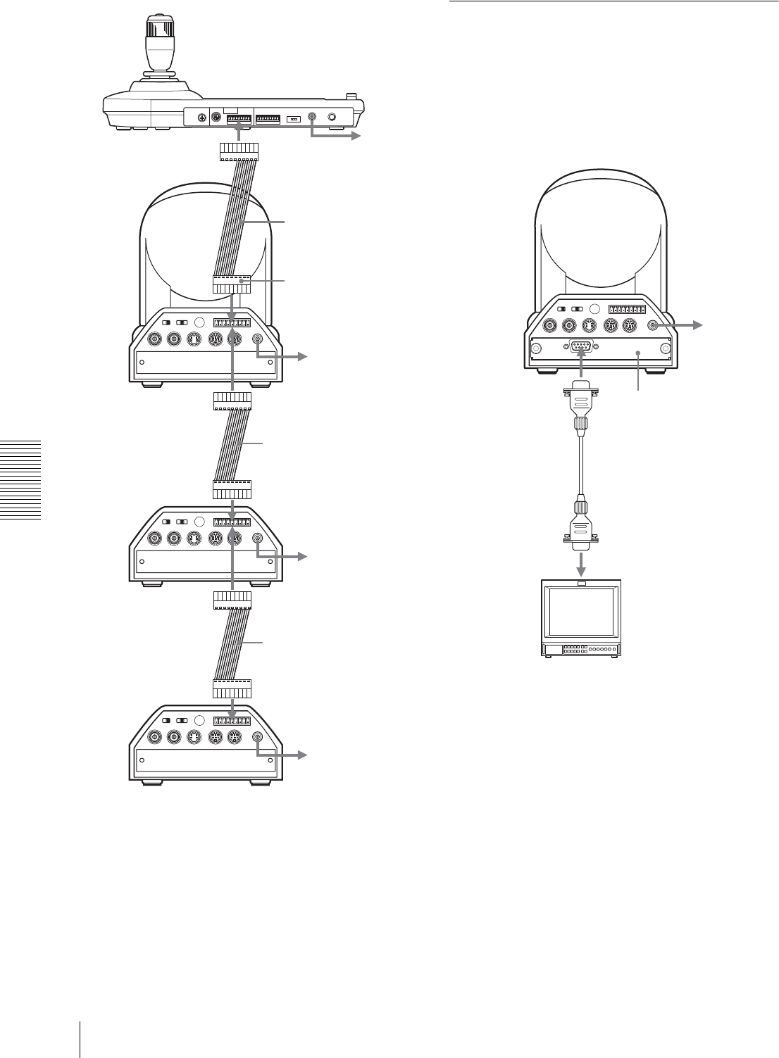
Connecting a Video Monitor
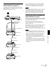
Equipped with Analog RGB/
Component Connectors
When you install an optional BRBK-301 Analog RGB
Component Card into the camera, you can output the
signal from the camera by converting it into component
video, RGB, composite video or S-video signal.
For details on how to attach the BRBK-301 Analog
RGB Component Card, see page 42.
To select the output signal, use the OUTPUT1 and
OUTPUT2 items in the ANALOG OUT menu
(page 30).
EXT SYNC IN
IR SELECT
75
1 2 3
OFF ON
IN VISCA RS-232C OUT
!
VISCA RS-422
1 2 3 4 5 6 7 8 9
DC IN
12V
R
VIDEO S VIDEO
EXT SYNC IN
IR SELECT
75
1 2 3
OFF ON
IN VISCA RS-232C OUT
!
VISCA RS-422
1 2 3 4 5 6 7 8 9
DC IN
12V
R
VIDEO S VIDEO
EXT SYNC IN
IR SELECT
75
1 2 3
OFF ON
IN VISCA RS-232C OUT
!
VISCA RS-422
1 2 3 4 5 6 7 8 9
DC IN
12V
R
VIDEO S VIDEO
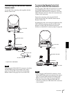
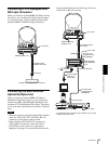
RM-BR300 Remote Control Unit
to AC outlet
VISCA RS-422
VISCA RS-422 cable
First BRC-300/300P
to AC outlet
Second BRC-300/300P
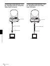
to AC outlet
VISCA RS-422 cable
Third to Seventh BRC-300/300P
to AC outlet
to VISCA RS-422
VISCA RS-422
VISCA RS-422
VISCA RS-422
VISCA RS-422 cable
EXT SYNC IN
IR SELECT
75
1 2 3
OFF ON
IN VISCA RS-232C OUT
!
VISCA RS-422
1 2 3 4 5 6 7 8 9
DC IN
12V
R
VIDEO S VIDEO
to AC outlet
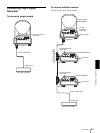
RGB/SYNC
BRBK-301 Analog
RGB Component Card
CCXC-9DD/9DB cable
with D-sub 9-pin plugs
(not supplied)
to RGB IN
Video monitor, etc.