


Installation and Connections
Connections
52
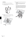
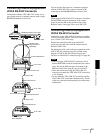
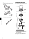
Notes on use of the CCFC-M100 Optical Fiber
Cable
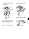
• In order to prevent cable transmission loss, fix the
bend in the cable keeping more than 40 mm (1 5/8
inches) radius.
• To connect two Optical Fiber Cables, use the
extension plug supplied with the cable.
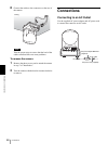
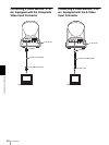
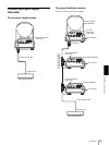
Connecting a Video Switcher
Use a commercially available video switcher to switch
between the multiple camera signals to be output.
For connection with a video switcher, refer to the
Operating Instructions of the switcher.
BRC-300/300P
CCFC-M100
Keep more than 40 mm
(1 5/8 inches) radius.
BRU-300/300P
CCFC-M100
A
B
Extension plug
MODE
VISCA
1919
RS-422 ON/OFF
TALLY/CONTACT
RS-232C
CONTACT(TALLY)
!
TAL LY
CONTACT DC IN 12V
EXT SYNC IN
IR SELECT
75
1 2 3
OFF ON
IN VISCA RS-232C OUT
!
VISCA RS-422
1 2 3 4 5 6 7 8 9
DC IN
12V
R
VIDEO S VIDEO
EXT SYNC IN
IR SELECT
75
1 2 3
OFF ON
IN VISCA RS-232C OUT
!
VISCA RS-422
1 2 3 4 5 6 7 8 9
DC IN
12V
R
VIDEO S VIDEO
EXT SYNC IN
IR SELECT
75
1 2 3
OFF ON
IN VISCA RS-232C OUT
!
VISCA RS-422
1 2 3 4 5 6 7 8 9
DC IN
12V
R
VIDEO S VIDEO
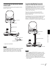
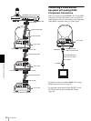
Third to Seventh
BRC-300/300P
to AC outlet
VISCA RS-232C IN
RS-232C cable
VISCA RS-232C OUT
Second BRC-300/300P
VISCA RS-232C IN
RS-232C cable
VISCA RS-232C OUT
First BRC-300/300P
75-ohm coaxial cable*
75-ohm coaxial cable*
RM-BR300 Remote
Control Unit
RS-232C cable
VISCA RS-232C IN
VISCA RS-232C
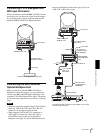
to CONTACT
to composite video input
T VIDEO
* You can also use an S-video connecting cable to connect the
S VIDEO connector on the camera and the S-video input
connector on the video switcher.
TALLY/CONTACT
75-ohm coaxial cable*
T VIDEO
Video switcher (commercially available)