


Overview
Location and Function of Parts
22
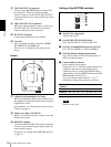
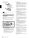
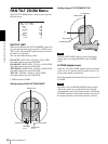
Switches 3 to 5 (Camera address selectors)
Set the address of the camera.
Normally set to "0". With this setting, addresses are
assigned to the cameras automatically in the
connected order by pressing the POWER button
while holding down the RESET button on the RM-
BR300 Remote Control Unit.
You can assign the camera address "1" to "7"
manually by setting these selectors as follows:
Note
Switch 6 is not used.
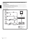
K VISCA RS-232C IN connector
Connect to the RM-BR300 Remote Control Unit
(not supplied). When you connect multiple
cameras, connect it to the VISCA RS-232C OUT
connector of the previous camera in the daisy chain
connection.
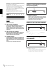
L VISCA RS-232C OUT connector
When you connect multiple cameras, connect it to
the VISCA RS-232C IN connector of the next
camera in the daisy chain connection.
M CAMERA connector
Connect to the optical connector of the BRBK-303
Optical Multiplex Card installed in the BRC-300/
300P camera using the CCFC-M100 Optical Fiber
Cable.
A dustproof cap is attached at the factory.
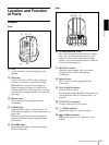
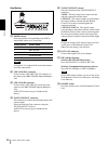
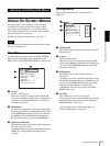
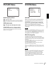
BRBK-301 Analog RGB Component
Card (not supplied)
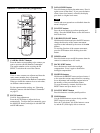
A RGB/SYNC connector
Supplies various analog signals such as composite
video, S video, component video and RGB signals.
The output signal can be selected with the
ANALOG OUT menu of the camera.
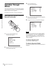
BRBK-302 SDI Card (not supplied)
A SDI connector
Supplies a signal conforming to SMPTE259M
serial digital interface standards.
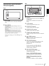
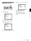
BRBK-303 Optical Multiplex Card
(not supplied)
A Optical connector
Performs the optical digital multiplex transmission
of video, external sync and control signals.
A dustproof cap is attached at the factory.
Camera
address
01234567
Switch 3 OFF ON OFF ON OFF ON OFF ON
Switch 4 OFF OFF ON ON OFF OFF ON ON
Switch 5 OFF OFF OFF OFF ON ON ON ON
1
RGB/SYNC
1
1