


11
MZ-R501/R501PC
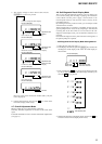
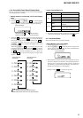
2 In the normal mode, turn on the [HOLD] switch. While press-
ing the [VOL --] key press the following order:
> t > t . t . t > t
. t > t . t X t X
SECTION 4
TEST MODE
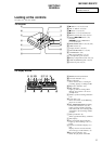
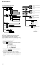
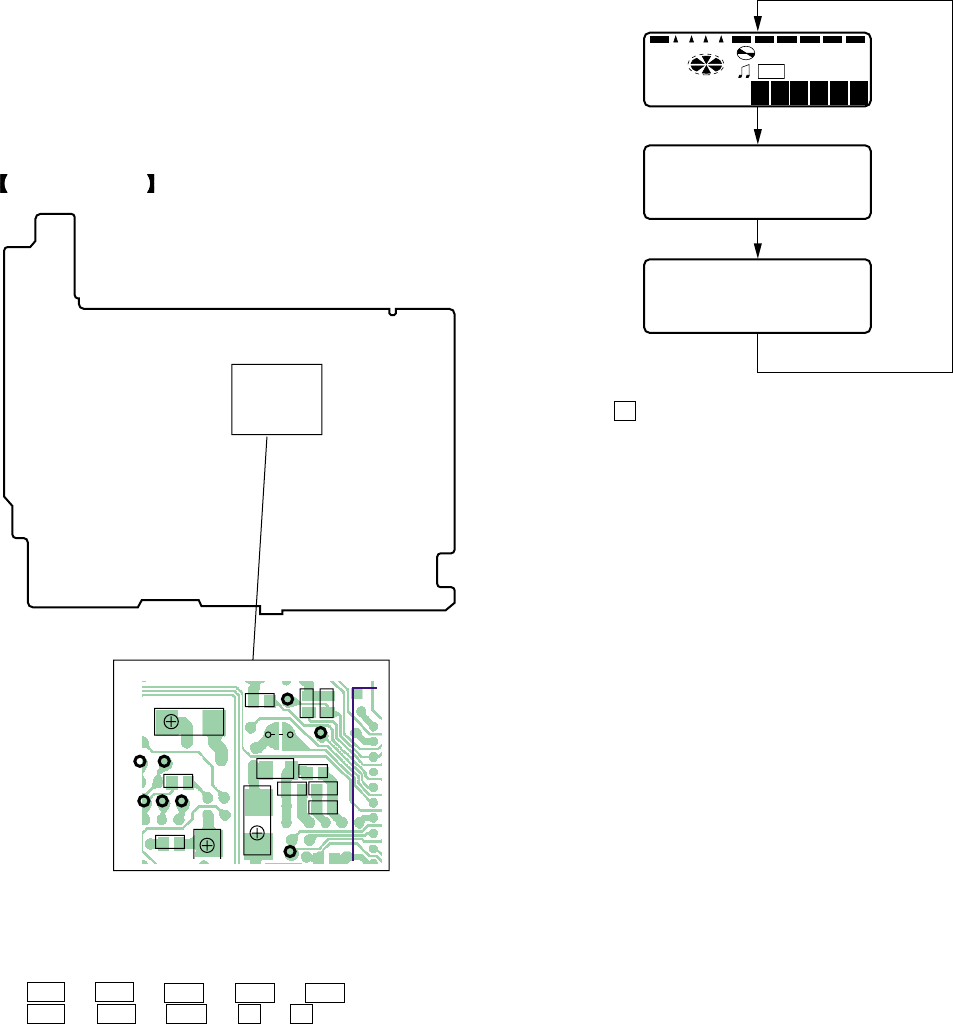
4-3. Operation in Setting the Test Mode
• When the test mode becomes active, first the display check mode
is selected.
• Other mode can be selected from the display check mode.
• When the test mode is set, the LCD repeats the following dis-
play.
• When the
X key is pressed and hold down, the display at that
time is held so that display can be checked.
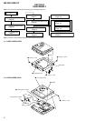
4-4. Releasing the Test Mode
For test mode set with the method 1:
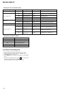
Turn off the power and open the solder bridge on TAP801 (TEST)
on the MAIN board.
Note: Remove the solders completely. Remaining could be shorted
with the chassis, etc.
For test mode set with the method 2:
Turn off the power.
Note: If electrical adjustment (see page 17) has not been finished
completely, always start in the test mode. (The set cannot
start in normal mode)
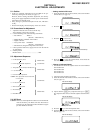
4-1. Outline
• This set provides the Overall adjustment mode that allows CD
and MO discs to be automatically adjusted when in the test mode.
In this overall adjustment mode, the disc is discriminate between
CD and MO, and each adjustment is automatically executed in
order. If a fault is found, the system displays its location. Also,
the manual mode allows each individual adjustment to be auto-
matically adjusted.
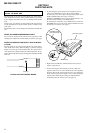
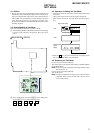
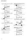
4-2. Setting Method of Test Mode
There are two different methods to set the test mode:
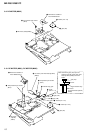
1 Short TAP801 (TEST) on the MAIN board with a solder bridge
(connect pin 3 of IC801 to the ground). Then, turn on the
power.
All lit
This set LCD display
All off
Microcomputer
version
display
SYNCMONO REC REMAIN
SHUFREC
u
1F
-a88 : 8 8
00 6
V1.300
R806
R807
C521
R805
R811
C808
R810
R830
C807
FB801
C815
C830
AP856
AP803
AP528
AP526
TAP801
(TEST)
AP802
AP531
AP530
AP529
MAIN BOARD (SIDE B)