


19
MZ-R501/R501PC
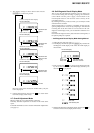
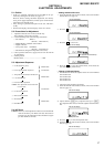
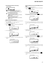
3. Adjust with [VOL +], [VOL --] key so that the adjusted value
(hexadecimal value) becomes the ambient temperature.
(Initial value: 14h = 20 °C, Adjusting range: 80h to 7fh (–128
°C to +127 °C)
4. Press the X key to write the adjusted value.
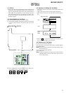
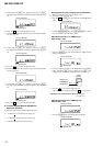
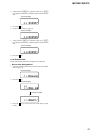
5-7. Laser Power Check
Connection :
Checking Method :
1. Select the manual mode of test mode (see page 12), and set the
laser power adjusting mode (item number 010).
2. Press the
. key continuously until the optical pick-up
moves to the most inward track.
3. Open the cover and set the laser power meter on the objective
lens of the optical pick-up.
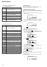
4. Press the N key, and set the laser MO read adjustment mode
(item number 011).
5. Press the [ENTER] key and set the address & adjusted value
display (See page 13).
6. Check that the laser power meter reading is 0.81 ± 0.08 mW.
7. Check that the voltage both ends (TP (+) and TP (–)) of resis-
tor R501 at this time is below 44 mV.
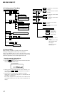
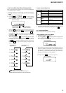
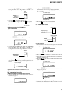
2. Connect a digital voltmeter to the TP902 (VC) on the MAIN
board, and adjust [VOL +] key (voltage up) or [VOL --] key
(voltage down) so that the voltage becomes 2.75 ± 0.01 V.
3. Press the X key to write the adjusted value.
(The item number changes to 764 when X key is pressed)
Adjustment and Connection Location:MAIN board
(see page 20)
• Adjustment method of Vl PWM Duty
(item number: 764)
1. Press the [ENTER] key and change the LCD display.
2. Connect a digital voltmeter to the TP901 (VL) on the MAIN
board, and adjust [VOL +] key (voltage up) or [VOL --] key
(voltage down) so that the voltage becomes 2.30 ± 0.01 V.
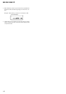
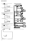
3. When press the X key to write the adjusted value, LCD dis-
plays as follows and power supply manual adjustment has com-
pleted.
Adjustment and Connection Location:MAIN board
5-6. Temperature Correction
• Adjustment Method of temperature correction
1. Select the manual mode of test mode, and set the mode num-
ber 014 (see page 12).
2. Measure the ambient temperature.
digital
voltmeter
MAIN board
TP902(VC)
TP910(GND)
This set LCD display
7 6 4
V1 PWM
This set LCD display
7 6 4
AD
: Adjusted value
digital
voltmeter
MAIN board
TP901(VL)
TP910(GND)
This set LCD display
0 0 0 ADJ OK
This set LCD display
0 1 4 SetTmp
: Address
14: Adjusted value
This set LCD display
0 1 4 S14
digital voltmete
r
MAIN board
TP(+)
TP(–)
laser
power meter
Optical pick-up
objective lens
This set LCD display
0 1 0
Laser
This set LCD display
0 1 1
LrefPw
This set LCD display
0 1 1 ###S
###: Address
: Adjusted value