


6
MZ-R501/R501PC
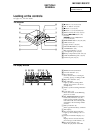
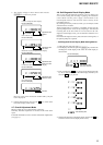
3-1. CASE (LOWER) ASSY
(Page 6)
3-2. CASE (UPPER) ASSY
(Page 6)
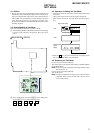
3-4. MAIN BOARD
(Page 7)
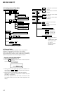
3-5. MD MECHANISM DECK
(Page 8)
3-6. SERVICE ASSY, OP
(Page 8)
3-7. HOLDER ASSY
(Page 9)
SET
3-10. DC MOTOR (M601)
(Page 10)
3-3. LCD MODULE
(Page 7)
3-9. DC MOTOR (M602)
(Page 10)
3-8. MOTOR FLEXIBLE BOARD
(Page 9)
DC MOTOR (M603)
(Page 10)
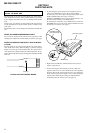
Note : This set can be disassemble according to the following sequence.
SECTION 3
DISASSEMBLY
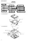
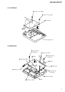
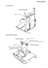
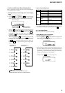
3-2. CASE (UPPER) ASSY
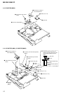
Note : Follow the disassembly procedure in the numerical order given.
3-1. CASE (LOWER) ASSY
2
screw (1.7), MI
1
screw (1.7), MI
3
screws (1.7), MI
knob (hold)
6
case(lower) assy
4
claw
5
1
screws (1.7), M
I
3
case (upper) assy
2
CN801
4
spring (POP-L), torsion
spring (POP-L), torsion
chassis assy