


18
MZ-R501/R501PC
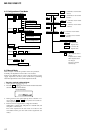
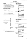
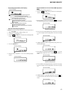
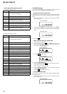
• Setting method of power supply manual adjustment
1. Make sure that the power supply voltage is 3V.
2. Set the test mode (see page 11).
3. Press the
. or [VOL--] key to activate the overall adjustment
mode.
4. Press the
[END SEARCH] key. (the [END SEARCH] key causes
the item number to be switched to 762.)
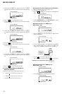
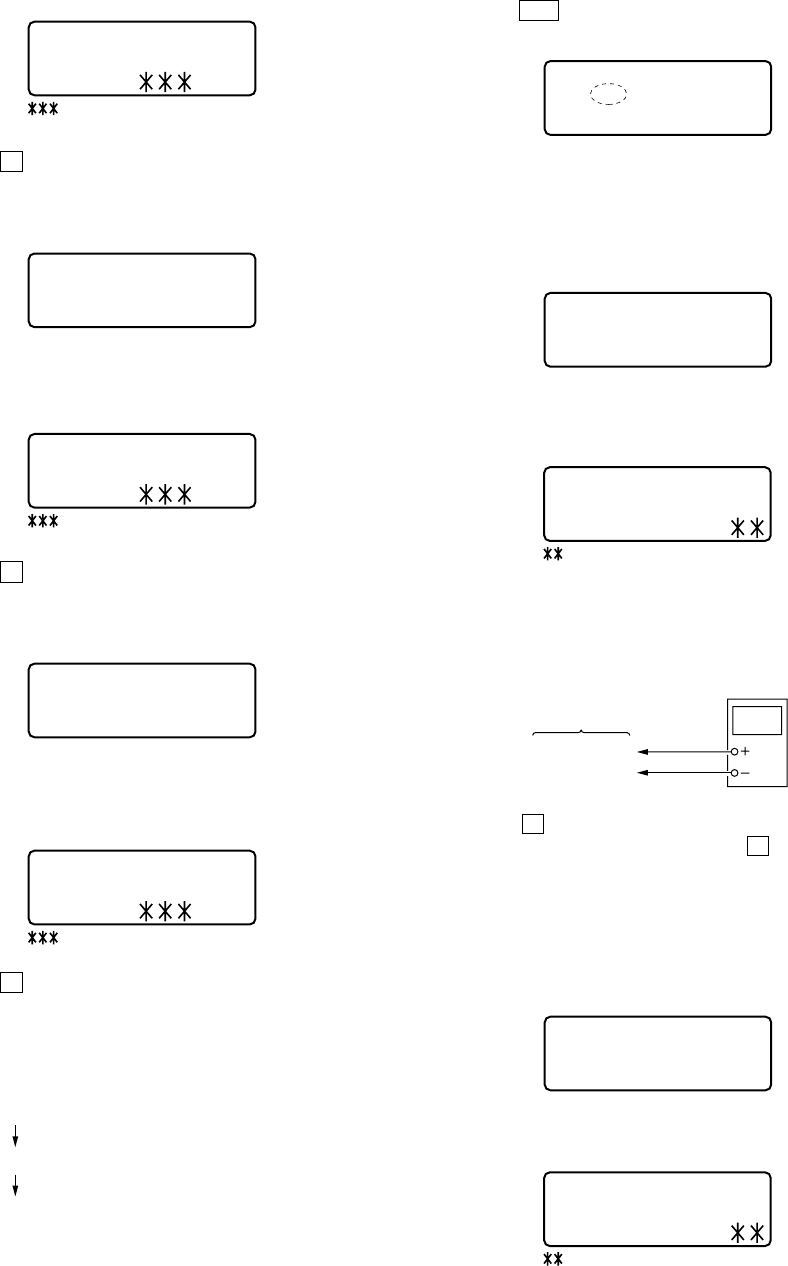
• Adjustment method of Vc PWM Duty (L)
(item number: 762)
1. Press the [ENTER] key and set the address & adjusted value
display (see page 13).
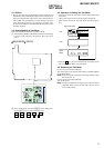
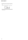
2. Connect a digital voltmeter to the TP902 (VC) on the MAIN
board, and adjust [VOL +] key (voltage up) or [VOL --] key
(voltage down) so that the voltage becomes 2.40 ± 0.01 V.
3. Press the X key to write the adjusted value.
(The item number changes to 763 when X key is pressed)
Adjustment and Connection Location:MAIN board
(see page 20)
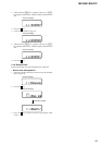
• Adjustment method of Vc PWM Duty (H)
(item number: 763)
1. Press the
[ENTER] key and change the LCD display.
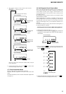
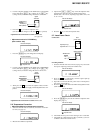
5) Adjust with the [VOL+] key (adjusted value up) or [VOL--]
key (adjusted value down) so that the adjusted value becomes
01.
6) Press the X key to write the adjusted value.
7) Select the manual mode of the test mode, and set item number
871 (see page 12).
8) Adjust with the [VOL+] key (adjusted value up) or [VOL--]
key (adjusted value down) so that the adjusted value becomes
20.
9) Press the X key to write the adjusted value.
10) Select the manual mode of the test mode, and set item number
872 (see page 12).
11) Adjust with the
[VOL+] key (adjusted value up) or [VOL--]
key (adjusted value down) so that the adjusted value becomes
39.
12) Press the X key to write the adjusted value.
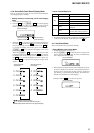
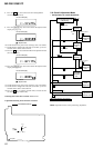
5-5. Power Supply Manual Adjustment
• Adjustment sequence
Adjustment must be done with the following steps.
2. Vc PWM Duty (H) adjustment (item number 763)
3. Vl PWM Duty adjustment (item number 764)
1. Vc PWM Duty (L) adjustment (item number 762)
digital
voltmeter
MAIN board
TP902(VC)
TP910(GND)
: Address
01: Adjusted value
This set LCD display
8 6 2 S01
This set LCD display
8 7 1 V5num
: Address
20: Adjusted value
This set LCD display
8 7 1 S20
This set LCD display
8 7 2
V5dat
: Address
39: Adjusted value
This set LCD display
8 7 2 S39
This set LCD display
0 0 0 Assy11
This set LCD display
7 6 2
Vc1PWM
This set LCD display
7 6 2 AD
: Adjusted value
This set LCD display
7 6 3
VchPWM
This set LCD display
7 6 3 AD
: Adjusted value