


20
MZ-R501/R501PC
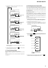
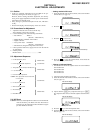
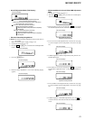
8. Press the N key, and set the laser CD read adjustment
mode (item number 012).
9. Press the [ENTER] key and set the address & adjusted value
display (see page 13).
10. Check that the laser power meter reading is 0.97 ± 0.10 mW.
11. Check that the voltage both ends (TP (+) and TP (–)) of resis-
tor R501 at this time is below 44 mV.
12. Press the N key, and set the laser MO write adjustment mode
(item number 013).
13. Press the [ENTER] key and set the address & adjusted value
display (See page 13).
14. Check that the laser power meter reading is 4.95 ± 0.50 mW.
15. Check that the voltage both ends (TP (+) and TP (–)) of resis-
tor R501 at this time is below 80 mV.
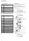
16. Press the
x key to quit the manual mode, and activate the
test mode (display check mode).
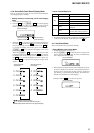
Checking and Connection Location: MAIN board
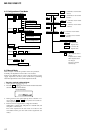
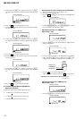
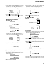
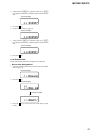
5-8. Overall Adjustment Mode
• Configuration of overall adjustment
Note: Adjust the CD first, when performing adjustment.
Adjustment/checking and Connection Location:
This set LCD display
0 1 2 HrefPw
This set LCD display
0 1 2 ###S
###: Address
: Adjusted value
This set LCD display
0 1 3 WritPw
This set LCD display
0 1 3 ###S
###: Address
: Adjusted value
TP910(GND)
TP902(VC)
TP
(
–
)
TP
(+)
TP901
(VL)
R501
MAIN BOARD (SIDE B)
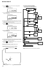
. key
> key
N key
N key
Protect switch
ON
Protect switch
OFF
x key
x key
x key
x key
x key
x key
NG item exists
or x key
Overall adjustment mode
(Title display)
CD overall
adjusting
MO overall
adjusting
CD overall
adjustment
OK
MO overall
adjustment
OK
CD overall
adjustment
NG
NG item exists
or x key
MO overall
adjustment
NG
Electrical
offset
adjustment
Power supply
adjustment
auto item feed
ENTER key
END SEARCH key
Test mode (display check mode)
All item
OK