


3
1. SERVICING NOTE......................................................... 4
2. GENERAL
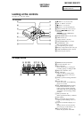
Looking at the Controls ...................................................... 5
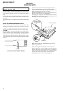
3. DISASSEMBLY
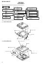
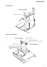
3-1. Case (Lower) Assy .............................................................. 6
3-2. Case (Upper) Assy .............................................................. 6
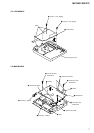
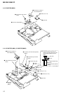
3-3. LCD Module ....................................................................... 7
3-4. Main Board .........................................................................7
3-5. MD Mechanism Deck ......................................................... 8
3-6. Service Assy, OP ................................................................. 8
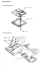
3-7. Holder Assy......................................................................... 9
3-8. Motor Flexible Board ..........................................................9
3-9. DC Motor (M602) ............................................................. 10
3-10. DC Motor (M601), DC Motor (M603) ............................. 10
4. TEST MODE
4-1. Outline............................................................................... 11
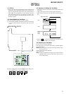
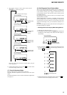
4-2. Setting Method of Test Mode ............................................11
4-3. Operation in Setting the Test Mode...................................11
4-4. Releasing the Test Mode ...................................................11
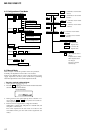
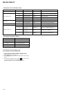
4-5. Configuration of Test Mode ..............................................12
4-6. Manual Mode ....................................................................12
4-7. Overall Adjustment Mode ................................................. 13
4-8. Self-Diagnosis Result Display Mode ................................13
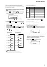
4-9. Reset the Error Display Code............................................14
4-10. Sound Skip Check Result Display Mode .......................... 15
4-11. Key Check Mode............................................................... 15
TABLE OF CONTENTS
5. ELECTRICAL ADJUSTMENTS
5-1. Outline............................................................................... 17
5-2. Precautions for Adjustment ............................................... 17
5-3. Adjustment Sequence ........................................................ 17
5-4. NV Reset ........................................................................... 17
5-5. Power Supply Manual Adjustment....................................18
5-6. Temperature Correction..................................................... 19
5-7. Laser Power Check ........................................................... 19
5-8. Overall Adjustment Mode ................................................. 20
5-9. Mode Settings ................................................................... 22
5-10. Resume Clear ....................................................................23
6. DIAGRAMS
6-1. IC Pin Function Description ............................................ 24
6-2. Block Diagram – Servo Section –..................................... 30
6-3. Block Diagram – Audio Section – .................................... 31
6-4. Block Diagram – System Control/Power Section – ..........32
6-5. Printed Wiring Board – Main Section – ............................ 34
6-6. Schematic Diagram – Main Section (1/3) – ......................36
6-7. Schematic Diagram – Main Section (2/3) – ......................37
6-8. Schematic Diagram – Main Section (3/3) – ......................38
7. EXPLODED VIEWS
7-1. Panel Section..................................................................... 43
7-2. Chassis Section .................................................................44
7-3. MD Mechanism Deck Section .......................................... 45
8. ELECTRICAL PARTS LIST......................................46
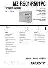
MZ-R501/R501PC