


QSP-660: Instructions for Basic Operation and Installation
Page 14
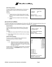
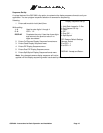
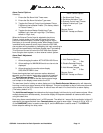
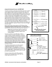
Set Alarm Hold Times
1: Hold Detected Alarms
for: 1 Sec.
2: Disable Detected Alarms
after: 0 Sec.
3: Hold Alarmed Images
for: 3 Sec.
Camera: Select
DISPLAY: Accept and Return
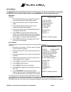
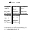
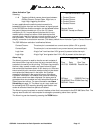
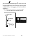
Alarm Control Options
1: Set Alarm Hold Times . . .
2: Set Alarm Activation Type . . .
3: External Control Input: Freeze
4: Master Enable Input Type:
Logic Low
Camera: Select
DISPLAY: Accept and Return
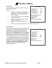
Alarm Control Options
Selecting:
1. Enters the Set Alarm Hold Times menu.
2. Enters the Set Alarm Activation Type menu.
3. Toggles the External Control Input between Picture
Freeze and alarm Master Enable. (The factory default
is “Picture Freeze”.)
4. Toggles the alarm Master Enable Input Type
between Logic Low and Logic High. (The factory
default is “Logic Low)
When the External Control Input is selected to be picture
Freeze, a single pulse on the input will freeze the current
picture on the main display. Another single pulse will return
the display to its normal updating mode. When Master Enable
is selected as the external control input, the entire QSP-660
alarm system will be enabled or disabled by this input according to
the logic level specified by the Master Enable Input Type setting.
This input can be used to control the QSP-660 alarm system
from a burglar alarm system, or other external control system.
Alarm Dwell Adjustment
Selecting:
1. Allows changing the alarm ACTIVATION HOLD time.
2. Allows setting of a MAXIMUM time for an alarm to be
displayed.
3. Allows changing the monitor alarm display
SEQUENCE DWELL time.
Some alarming devices (such as some motion detectors)
generate very brief alarms lasting only a fraction of a second.
The
Hold Detected Alarms
time is the amount of time that
the alarm event will be held so that the alarm camera image
can be kept on the display screen and to the VCR.
The maximum time for holding an alarm display set in the
Disable Detected Alarms
option will determine
how long a continuous alarm camera will be displayed. This can be adjusted so that a continuous alarm will
not consume all of the VCR’s record time. A value of zero will result in no time limit for an alarm display.
(The factory default is “0”).
The
Hold Alarmed Images
time determines the image display hold time during multi-camera alarms. When
multiple alarms occur simultaneously, the monitor display will sequence between all cameras with alarms
using this dwell time.
Both delay times are adjustable from 1 to 255 seconds. The default is 1 second for the activation hold and 3
seconds for the sequence dwell time.
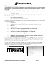
Camera buttons
are used to enter digits 1 through 4 (5-8 is VCR +1-
4) the
QUADRANT
button is used to enter digit 9, and the
PIP
button is used to enter 0. The
DISPLAY
button stops the editing of a delay value.