


QSP-660: Instructions for Basic Operation and Installation
Page 21
E
QUIPMENT
R
EQUIREMENTS
The QSP-660 is designed to be compatible with all EIA and CCIR compatible equipment. The QSP-660 will
accept 2:1 interlace cameras in either a line-locked or free running (internal reference) modes. The use of
random interlace camera is not recommended unless the line lock is turned off.
S
PECIFICATIONS
Physical
Dimensions...........................................................11-5/16 w X 9 d X 2-3/8 h
(288 mm X 229 mm X 61 mm)
Weight .................................................................2.6 lbs. (1.17 kg), Power Supply: 1.0 lbs. (0.45 kg)
Operating Temp ...................................................32°F - 104°F (0°C - 40°C)
Video
Signal Format.......................................................EIA/CCIR Compatible Monochrome
EIA: 525 lines, 60 Fields / sec.
CCIR: 625 lines, 50 Fields / sec.
Camera Inputs......................................................0.6 to 1.2 Vp-p 75 Ohm Termination
Monitor Output......................................................1.2 Vp-p into 75 Ohms
Digital Sampling ...................................................512H x 512V x 8 Bits (256 Gray Levels)
Refresh Rate ........................................................30 Fields Per Second (EIA)
25 Fields Per Second (CCIR)
Electrical
Power ...................................................................12 V AC @ 2 Amp
Safety ...................................................................110V, 60Hz Power Supply: UL Listed and CSA Certified
220V, 50Hz Power Supply: CE Mark and VDE approved
EMI .......................................................................FCC Part 15, Class A
CE Certified EN50081-1 (emissions), EN50082-1 (immunity)
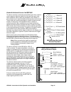
Connectors
Video In ................................................................BNC, 1 Per Camera, Terminating, or Hi Z (4 Total)
Loop Thru .............................................................BNC, 1 Per Camera
Monitor Video Out ................................................BNC
VCR Video Out.....................................................BNC
VCR Video In........................................................BNC
Serial Port.............................................................DB9
Alarm ....................................................................DB15 with Screw On Adapter Board
12 VAC, or 12 VDC ..............................................Power Jack, 0.080 Pin Diameter
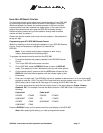
Controls
DISPLAY ..............................................................Return to Quad Display
SEQUENCE .........................................................Calls Up Selected Sequence Mode
FREEZE ...............................................................Freeze current display image
PIP........................................................................Calls Up Next PIP Mode
QUADRANT .........................................................Rotates Quadrant
ZOOM...................................................................Activates Zoom
VCR......................................................................Enables/Disables VCR Input for Recorder Playback
FOUR CAMERA BUTTONS (1-4)........................Calls Up Individual Cameras Full Screen
IR Remote ............................................................Duplicates Front Panel Controls
Termination Switches...........................................Selects 75 Ohm or Hi-Z Termination for 4 Video Inputs