


QSP-660: Instructions for Basic Operation and Installation
Page 20
RS-232 R
EMOTE
C
ONTROL
I
NTERFACE
The QSP-660 has a built in RS-232 serial interface that supports remote control of the QSP-660 through simple
ASCII commands. These commands provide access to the front panel button operations just as the IR Remote
Control does.
The QSP-660 serial interface is fixed at 2400 baud, 8 bits, 1 stop bit, and no parity. It uses the very simple
command format:
<command> <return>
The command is 2 character or 2 character plus parameter and must be followed by a carriage return. The
QSP-660 will respond with:
> if the command was recognized, or
? if the command was not recognized or is invalid
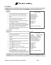
The following commands are supported by the QSP-660 serial interface and behave just as if the indicated front
panel button was pushed:
BD
Display
button
BS
Sequence
button - will cause QSP-660 to start or stop sequencing during live mode.
BP
PIP
button
BQ
Quadrant
button
BV
VCR
button - will cause the QSP-660 to enter or exit VCR playback mode
BF
Freeze
button - will cause the QSP-660 to freeze during live mode
BB
VCR
button - will cause the QSP-660 to enter the VCR bypass mode
BC n
Camera
buttons - is a number 1 through 4 corresponding to the camera number. A space or tab
must be entered between the command and the number.
BZ
Zoom
button – will expand a quadrant of any image in playback. Repeated entries of this
command will rotate through the quadrants.
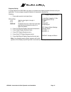
Commands only take a fraction of a second to execute within the QSP-660. However, there must be a
delay of at least 0.3 seconds (300 milliseconds) between the carriage return and start of the next
command.
The command decode prompt (>) may occur before the command has finished executing and
should not be used as an indication to send the next command.
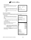
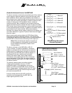
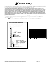
For proper RS-232 operation, the 8 position DIP switch, SW 5, located next to the DB-9 RS-232 interface
connector within the QSP-660 must be set to the factory default positions as indicated below. The DB-9
connector pinout corresponds to a standard 9-pin DCE (modem) device.
ON
42 53 6 7 81
SW 5
SERIAL CONNECTOR PINS
1 Signal ground
2 TX+ (out) RS232 or 422
3 RX+ (in) RS232 or 422
4 Signal ground
5 Signal ground
6 Signal ground
7 TX- (out) RS422
8 RX- (in) RS422
9 Signal ground