


QSP-660: Instructions for Basic Operation and Installation
Page 18
A
LARM
I
NTERCONNECTION ON THE
QSP-660
The alarm connector on the back panel allows input of four external
control signals to affect the behavior of the real time quad under
alarm conditions. Alarm inputs are provided for each camera. A
picture freeze input is also provided to allow the picture to be frozen.
These inputs are normally generated by a switch located at a door,
window, or other point in the installation where a camera is
monitoring activity. Many installations use an open switch that
requires a switch closure to activate the alarm. As part of the QSP-
660’s normal alarm video processing, an alarm output is generated
on the same back panel connector. In addition to the alarm inputs, a
picture freeze input is also provided. While picture freeze is
activated, any present camera image is retained on the display and
new video information is ignored. A picture freeze does not trigger
the alarm output.
Alarm inputs contain series resistors for ESD (Electro Static
Discharge) and lightning damage protection. The outputs also
contain series resistors to limit output current to prevent damage to
the QSP-660 in the occurrence of shorting out the output pin.
Note:
When connecting the inputs and outputs up
to other equipment, consideration should be given
to the limitations introduced by these current-
limiting resistors.
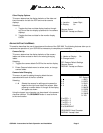
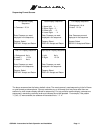
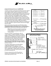
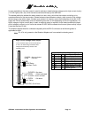
The alarm connector on the QSP-660 is a DB-15,
15-pin connector. For ease of installation, a breakout
adapter is provided with the 16th terminal connected to
chassis ground. A simple alarm connection is shown to
the right using the QSP-660 alarm breakout adapter. In
the example to the right, switches are connected
directly to the alarm inputs, and a single output is
connected to some signaling device or to a controlled
piece of equipment. In this case, an external resistor is
required to pull the output up to +5V (High) indicating a
non-alarm condition.
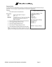
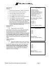
The external resistor makes connection to higher
voltage systems possible, such as a 12 VDC
automobile system. In this application, the pull-up
resistor is not tied to the QSP-660 +5V pin, but to the
higher voltage system. Voltages greater than +5V must
not exceed 30 VDC and the current through the output
pin must not exceed 50 mA.
Failure to remain within the 30 VDC and 50 mA
restriction could damage either the QSP-660, the
output signaling device, or both.
9
9
Typical Alarm Connections
using the Breakout Adapter
Alarm Switches
OPEN = no alarm
CLOSED = alarm activate
1KOhm
+Vsupply
(30VDC, 50mA max)
Alarm Output
(
To indicator
,
VCR
,
etc.
)
+5V = Hi
g
h = no alarm
0V = Low = alarm activated
Alarm Output
Vout = Hi
g
h = no alarm
0V = Low = alarm activated
1
16
1
16
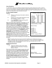
1: Alarm #1
2: Alarm #2
3: Alarm #3
4: Alarm #4
1K Ohm
100 Ohm
100 Ohm
+5V
10: Picture freeze
13: Alarm out pwr
15: Alarm
g
round
9: Alarm output
QSP-660 Alarm Port Internal
Electrical Equivalent
(50 mA maximum)