


QSP-660: Instructions for Basic Operation and Installation
Page 5
4. If your VCR has internal on-screen menus for its set up, use the
VCR Bypass
feature of the
QSP-660 to view the VCR’s on-screen menus on the display monitor. See the “VCR Bypass
Function” description on page 3.
5. At this point, the basic configuration of your QSP-660 is complete. You may now proceed to set
more advanced functions as required for your installation (alarms, camera labels, etc.) Refer to
the
Advanced Function menus
starting on page 9 for detailed information.
B
ACK
P
ANEL
C
ONNECTIONS
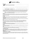
The four-camera input BNC connectors are labeled LOOP and the factory default configuration is 75 ohm
termination ON. One DIP switch and three jumpers inside the unit (see section below) determine whether each
inputs’ 75 ohm termination is ON or OFF.
Connect the QSP-660 VCR IN to the video output of the VCR and the QSP-660 VCR OUT to the video input of
the VCR. The alarm connector is a standard DB-15, which will mate with the included alarm wire adapter board
or standard computer-type cable. See page 18 for further alarm connection information.
V
IDEO
L
INE
T
ERMINATION
S
WITCHES
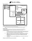
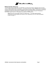
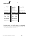
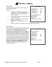
*This switch must be in the position shown for proper QSP-660 operation.
The video line termination switches/jumpers for each camera input are located in the rear of the unit and are
accessed by removing the top cover. The switches/jumpers are in the order shown above when looking down
on the circuit board. The above switches/jumpers are shown in the factory default settings (75 ohm terminations
ON).
Note:
There is an additional termination switch for the VCR input on position 4 of SW 4.
1
2
3
4
Camera 3
Camera 2
Camera 1
SW4
JP3
JP2 JP1
Unused*
Unused*
Camera 4
VCR