


QSP-660: Instructions for Basic Operation and Installation
Page 19
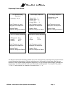
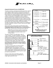
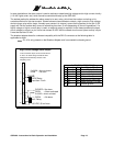
In some installations, the alarm output is used to activate or deactivate high voltage and/or high current circuitry
(110 VAC lights, siren, etc.) which cannot be controlled directly by the QSP-660.
The easiest method to address the above cases is to use a relay, which has the number and rating on its
contacts sufficient for the alarm output. Shown below are two methods to control a high current or high voltage
device using a relay with a single, normally open contact. An internal, current limiting resistor for the pin 9 +5V
supply will limit the usable relay current to something less than 10 mA (depending on the coil impedance). If a
higher voltage or higher current relay is used, an external supply is required. Under these conditions the open
circuit voltage (no alarm) on pin 9 must not exceed 30 VDC and the closed circuit current (alarm active) into pin
9 must be less than 50 mA.
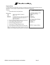
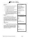
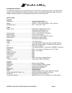
The breakout adapter board is numbered compatibly with the DB-15 connector so the following table is
applicable to either.
Note
: Pin 16 is only present on the Breakout Adapter and is connected to chassis ground.
9
9
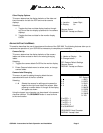
High Current/Voltage Alarm Output
To be used when output current exceeds 50 mA
or when, non-alarm voltage exceeds 30 VDC.
Voltage/Current limited by contacts of the
relay being used.
Less than 10 mA
5 VDC Relay
CLOSED = Alarm activated
OPEN = No alarm
Vout Relay
CLOSED = Alarm activated
OPEN = No alarm
CLOSED = No alarm
OPEN = Alarm activated
1
16
1
16
Vout
-
+
+30 VDC, 50 mA max.
ALARM CONNECTOR PINS
1 Alarm1 9 Alarm Out (< 50 mA)
2 Alarm2 10 Freeze/Master Enable
3 Alarm3 11 (reserved for future use)
4 Alarm4 12 (reserved for future use)
5 NA 13 +5V ( < 10 mA)
6 NA 14 (reserved for future use)
7 NA 15 Signal ground (< 10 mA)
8 NA 16 Chassis ground