


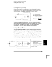
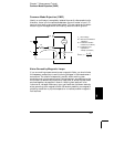
Removing Test Lead Resistance Errors
To eliminate offset errors associated with the test lead resistance in
2-wire ohms measurements, follow the steps below.
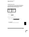
1. Short the ends of the test leads together. The multimeter displays the
test lead resistance.
2. Press
Null from the front panel. The multimeter displays “0”
ohms with the leads shorted together.
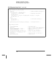
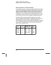
Power Dissipation Effects
When measuring resistors designed for temperature measurements
(or other resistive devices with large temperature coefficients), be aware
that the multimeter will dissipate some power in the device-under-test.
If power dissipation is a problem, you should select the multimeter’s
next higher measurement range to reduce the errors to acceptable
levels. The following table shows several examples.
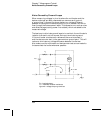
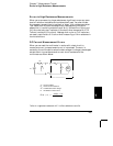
Settling Time Effects
The 34401A has the ability to insert automatic measurement settling
delays. These delays are adequate for resistance measurements with less
than 200 pF of combined cable and device capacitance. This is particularly
important if you are measuring resistances above 100 k
Ω. Settling due to
RC time constant effects can be quite long. Some precision resistors and
multi-function calibrators use large parallel capacitors (1000 pF to 0.1
µF)
with high resistor values to filter out noise currents injected by their
internal circuitry. Non-ideal capacitances in cables and other devices may
have much longer settling times than expected just by RC time constants
due to dielectric absorption (soak) effects. Errors will be measured when
settling after the initial connection and after a range change.
Range
100
Ω
1 k
Ω
10 kΩ
100 k
Ω
1 M
Ω
10 MΩ
Test Current
1 mA
1 mA
100
µA
10
µA
5
µA
500 nA
DUT
Power at Full Scale
100 µW
1 mW
100
µW
10
µW
30
µW
3
µW
Chapter 7 Measurement Tutorial
Removing Test Lead Resistance Errors
204