


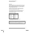

Integration Time
Integration time is the period during which the multimeter’s analog-to-
digital (A/D) converter samples the input signal for a measurement.
Integration time affects the measurement resolution (for better resolution,
use a longer integration time), and measurement speed (for faster
measurements, use a shorter integration time).
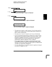
Applies to all measurement functions except ac voltage, ac current,
frequency, and period. The integration time for the math operations
(null, min-max, dB, dBm, limit test) is the same as the integration time
for the measurement function in use.
• Integration time is specified in number of power line cycles (NPLCs).
The choices are 0.02, 0.2, 1, 10, or 100 power line cycles. The default
is 10 PLCs.
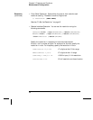
• The integration time is stored in volatile memory; the multimeter
selects 10 PLCs when power has been off or after a remote
interface reset.
• Only the integral number of power line cycles (1, 10, or 100 PLCs)
provide normal mode (line frequency noise) rejection.
• The only way to control the reading rate for ac measurements is by
setting a trigger delay (see page 79).
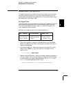
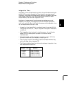
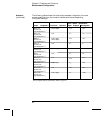
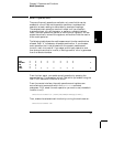
• The following table shows the relationship between integration time
and measurement resolution.
Integration Time
0.02 NPLC
0.2 NPLC
1 NPLC
10 NPLC
100 NPLC
Resolution
0.0001 x Full-Scale
0.00001 x Full-Scale
0.000003 x Full-Scale
0.000001 x Full-Scale
0.0000003 x Full-Scale
3
Chapter 3 Features and Functions
Measurement Configuration
57